Woxcon CHC2 Manual de usuario

CHC2
18G In-line HDMI Controller with
Auto Display Control
All Rights Reserved
Version: CHC2_2019V1.2
User Manual

18G In-line HDMI Controller with Auto Display Control
Table of Contents
1. Product Introduction .................................................................................................... 1
1.1 Features ............................................................................................................. 1
1.2 Package List ....................................................................................................... 1
2. Tec hn ic al S pe cific ation ................................................................................................ 2
3. Panel Description ........................................................................................................ 3
3.1 Front Panel ......................................................................................................... 3
3.2 Rear Panel .......................................................................................................... 4
4. System Connection ..................................................................................................... 5
4.1 System Diagram ................................................................................................. 5
4.2 IR Detector Connection ...................................................................................... 5
5. DIP Switch Operation .................................................................................................. 8
5.1 EDID Management ............................................................................................. 8
5.2 HDCP Mode ....................................................................................................... 9
6. System Control Setting .............................................................................................. 10
6.1 RS232 Command Setting ................................................................................. 11
6.1.1 Trigger Method Setting ........................................................................... 11
6.1.2 CEC Control Setting ............................................................................... 12
6.1.3 RS232 Control Setting ........................................................................... 13
6.1.4 IR Control Setting ................................................................................... 14
6.1.5 Relay Control Setting ............................................................................. 15
6.1.6 System Command .................................................................................. 16
6.2 Front Panel IR Learning ................................................................................... 16
7. Firmware Upgrade ..................................................................................................... 17

18G In-line HDMI Controller with Auto Display Control
1
1. Product Introduction
Thanks for choosing the CHC2 18G In-line HDMI Controller, which is designed for
automatic system control and HDMI signal extension in small meeting rooms and
huddle spaces. The controller supports three system trigger methods, IR signal, video
signal (5V or TMDS). It automatically triggers CEC commands, pre-loaded RS232 and
IR commands to turn on or off display, and relay control to rise and fall the projection
screen. It supports video resolution up to 4K@60Hz 4:4:4 HDR 10 and Dolby Vision,
and features 4K to 1080P down-scaling for compatibility with 1080P display. Besides
passing EDID information from the display, there are multiple built-in EDID settings
can be selected by the 4-pin DIP switch on the front panel. In addition, the controller
supports CEC control, RS232 control, IR learning and relay control.
1.1 Features
l Supports up to 4Kx2K@60Hz 4:4:4 HDR10 and Dolby Vision, HDCP 2.2 compliant.
l HDCP pass-through or converted to HDCP 1.4 for better compatibility.
l Supports 4K to1080P down-scaling.
l Comprehensive EDID management with 8 EDID Options for various application.
l Automation display control via CEC, RS232 and IR.
l Contact Closure input for connections with a variety of devices, such as sensor and
switch.
l Relay control for device like projection screen.
l Built-in signal equalizer, provides capability to use longer range HDMI cable.
1.2 Package List
l 1x 18G In-line HDMI Controller
l 2x Mounting Ears with 4 Screws
l 4x Plastic Cushions
l 3x 3-pin Terminal Blocks
l 1x RS232 Cable (3-pin to DB9)
l 1x Power Adapter (5V DC 1A)
l 1x IR Detector (Sold separately)
l 1x User Manual
Note: Please contact your distributor immediately if any damage or defect in the
components is found.

18G In-line HDMI Controller with Auto Display Control
2
2. Technical Specification
Video Input
Input
(1) HDMI IN
Input Connector
(1) Female type-A HDMI
Input Video Resolution
Up to 4Kx2K@60Hz 4:4:4 8bit
Video Output
Output
(1) HDMI OUT/CEC
Output Connector
(1) Female type-A HDMI
Output Video Resolution
Up to 4Kx2K@60Hz 4:4:4 8bit
Control
Control
(1) SET Button, (1) 4-pin DIP Switch, (1) FW, (1) IR OUT,
(1) RS232, (1) Sensor, (2) Relay (1~2)
Control Connector
(1) Type-A USB, (1) 3.5mm mini jack, (4) 3-pin terminal blocks
General
HDMI Standard
2.0
HDCP Version
2.2
HDCP Pass-through
Supported
CEC Control
Supported
Hot-plug
Supported
Bandwidth
18Gbps
HDMI Cable Length
1080P@60Hz ≤ 33 feet (10 meters),
4K@60Hz ≤ 16 feet (5 meters)
Operation Temperature
-5℃ ~ +55℃
Storage Temperature
-25℃ ~ +70℃
Relative Humidity
10%-90%
Power Supply
Input:100V~240V AC; Output: 5V DC 1A
Power Consumption
2.5W(Max)
Dimension (W*H*D)
120mm x 28mm x 84mm
Net Weight
305g
Note: Please adopt high-qualified HDMI cable fully compliant with HDMI2.0 for reliable transmission
and connection.

18G In-line HDMI Controller with Auto Display Control
3
3. Panel Description
3.1 Front Panel
①
POWER LED: The LED illuminates green when power is applied.
②
HDMI OUT LED: The LED illuminates blue when there is HDMI signal output.
③
SENSOR: Built-in IR sensor to receive IR signal.
④
DISPLAY ON LED: The LED blinks blue when the controller is in IR learning
mode, and it will illuminate blue after successfully learning the IR command.
⑤
DISPLAY OFF LED: The LED blinks blue when the controller is in IR learning
mode, and it will illuminate blue after successfully learning the IR command.
⑥
SET: Press the button to enable IR learning mode. Please refer to chapter 6.2 for
more details.
⑦
4-pin DIP switch for EDID setting and HDCP mode selection.
⑧
FW: Type-A USB port for firmware upgrade.
HDMI OUT
FW
ON
OFF
1
0
1 2 3 4
IR LEARNING
DISPLAY
ON
SENSOR
SET
DISPLAY
OFF
12345 6 78

18G In-line HDMI Controller with Auto Display Control
4
3.2 Rear Panel
①
HDMI IN: Type-A female HDMI input port to connect HDMI source device.
②
HDMI OUT/CEC: Supports CEC. Type-A female HDMI output port to connect
HDMI display.
③
IR OUT: 3.5mm mini jack to connect the IR emitter to send IR signal.
④
RS232: 3-pin terminal block to connect the RS232 control device (e.g. PC) or a
device (e.g. projector) to be controlled by RS232 commands.
⑤
Sensor: 3-pin terminal block to connect external IR detector (sold separately).
⑥
Relay 1~2: Two 3-pin terminal blocks to connect projection screen for relay
control.
⑦
DC 5V: DC connector for the power adapter connection.
DC 5V
NO C NC
RS232Sensor
Relay 1Relay 2
12V Sig
HDMI IN
Tx Rx NO C NC
HDMI OUT / CEC
123
4
7
5 6

18G In-line HDMI Controller with Auto Display Control
5
4. System Connection
4.1 System Diagram
The following diagram illustrates typical input and output connections that can be
utilized with this controller:
4.2 IR Detector Connection
The “Sensor (3-pin)” port of controller can be connected to an external IR detector
(sold separately). Here is a brief introduction about it.
The product is a stable PIR intrusion detector, using advanced signal analysis and
processing technology, providing ultra-high detection and anti-false alarm performance.
When an intruder passes through the detection area, the detector will automatically
detect human activities in the area and send an alarm signal to the controller. The IR
detector is widely used in family homes, villas, factories, shopping malls, office
buildings, warehouses and other places of security precautions.

18G In-line HDMI Controller with Auto Display Control
6
Technical Specification
Voltage
12V ~ 16V DC
Current
< 20mA
Detection Distance
12 meters
Detection Angle
360°
Alarm Indication
Red LED
Coverage Area
Remote area:11;
Middle area:8;
Near area: 5
Operation Temperature
-10℃ ~ +55℃
Environment Humidity
95%RH (Max)
Anti-RF
10MHZ~1GHZ 20V/M
Installation Method
Ceiling Mount
Installation Height
2.4~4.8 meters
Alarm Output
N.O./N.C. Touch spot: 30VDC 100MA
Tam p er Output
N.C. Tou c h spot: 30VDC 100MA
Dimension
Diameter 100mm* Height 34mm
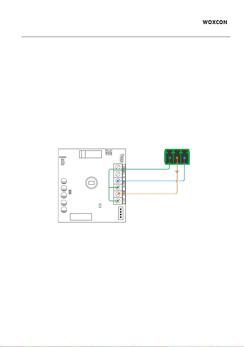
Wiring diagram
①
Ter mina l Bl ocks :
l +12V: Power positive input
l GND: Power negative input
l ALARM: Alarm output connector
l TAMPER: Tamper switch
connector
②
LED indicator
③
Relay
④
PIR Sensor
⑤
LED jumper wire
⑥
Normal Open (N.O.)/Normal Close
(N.C.) jumper wire
⑦
PLUSE jumper wire
⑧
Tam p er Swit ch
⑨
Thermistor
6
5
1
3
7
8
9
4
2

18G In-line HDMI Controller with Auto Display Control
7
Installation Circumstance
l Do not install outdoors and stay away from pets, air conditioners, heat sources,
rotating objects and direct sunlight.
l Mounting surface should be strong and non-loose and non-vibration.
l Install the IR detector in a place where the intruder is easy to pass through.
Installation Procedure
1) Open the bottom cover of the IR detector.
2) Make hole in the bottom cover for cable outlet.
3) Select the appropriate installation position and install the bottom cover.
4) According to the below wiring diagram, connect it to the controller.
5) Install the upper cover.
Sensor
12V Sig
IR Detector
Controller

18G In-line HDMI Controller with Auto Display Control
8
5. DIP Switch Operation
5.1 EDID Management
The Extended Display Identification Data (EDID) is used by the source device to
match its video resolution with the connected display. By default, the source device
obtains its EDID from the first connected display. Meanwhile, since the display with
different capabilities is connected to the controller, the DIP switch on the front panel
can be used to set the EDID to a fixed value to ensure the compatibility in video
resolution.
The switch represents “0” when in the lower (OFF) position, and it represents “1” while
putting the switch in the upper (ON) position.
Switch 1~3 are used for EDID setting. The DIP switch status and its corresponding
setting are shown at the back of the product.
Switch Status
Video Resolution
Audio Format
000
Pass Through
001
1080P
2CH
010
1080P
Multi-CH
011
3840x2160@30Hz HDR
2CH
100
3840x2160@30Hz HDR
Multi-CH
101
3840x2160@60Hz HDR
2CH
110
3840x2160@60Hz HDR
Multi-CH
111
User-defined EDID (Upload the EDID by type-A USB port)
1 2 3
EDID Setting
Default
1 2 3 4
ON
OFF
1
0
ON
OFF
4
HDCP Active
HDCP Passive
Pass Through
1080p 2CH
4K/30Hz HDR 2CH
ON
OFF
1 2 3
ON
OFF
1 2 3
ON
OFF
1 2 3
ON
OFF
1 2 3
1080p Multi-CH
ON
OFF
1 2 3
ON
OFF
1 2 3
ON
OFF
1 2 3
4K/30Hz HDR Multi-CH
4K/60Hz HDR 2CH
4K/60Hz HDR Multi-CH
ON
OFF
1 2 3
User Defined
Tabla de contenidos