WoMaster DS410F Manual de usuario

COVER
DS410F
Industrial 10-port Full Gigabit L2 Managed Fiber/Ethernet Switch
Nov.23.2018 V.1.0
WOM ASIA Co., Ltd
1F., No.185-3, Kewang Rd., Longtan Dist., Taoyuan 325, Taiwan

2
WoMaster
DS410F Industrial 10-port Full Gigabit L2 Managed Fiber/Ethernet Switch
User Manual
Copyright Notice
© WoMaster. All rights reserved.
About This Manual
This user manual is intended to guide a professional installer to install and to configure the DS410F switch.
It includes procedures to assist you in avoiding unforeseen problems.
NOTE:
Only qualified and trained personnel should be involved with installation, inspection, and repairs of this
switch.
Disclaimer
WoMaster reserves the right to make changes to this Manual or to the product hardware at any time without notice.
Information provided here is intended to be accurate and reliable. However, it might not cover all details and
variations in the equipment and does not claim to provide for every possible contingency met in the process of
installation, operation, or maintenance. Should further information be required or should particular problem arise
which are not covered sufficiently for the user’s purposes, the matter should be referred to WoMaster. Users must be
aware that updates and amendments will be made from time to time to add new information and/or correct possible
unintentional technical or typographical mistakes. It is the user’s responsibility to determine whether there have
been any such updates or amendments of the Manual. WoMaster assumes no responsibility for its use by the third
parties.
WoMaster Online Technical Services
At WoMaster, you can use the online service forms to request the support. The submitted forms are stored in server
for WoMaster team member to assign tasks and monitor the status of your service. Please feel free to write
to help@womaster.eu if you encounter any problems.

3
TABLE OF CONTENTS
COVER.......................................................................................................................................................................1
TABLE OF CONTENTS .................................................................................................................................................3
1.INTRODUCTION .....................................................................................................................................................5
1.1 OVERVIEW ......................................................................................................................................................5
1.2 MAJOR FEATURES ...........................................................................................................................................6
2. HARDWARE INSTALLATION....................................................................................................................................7
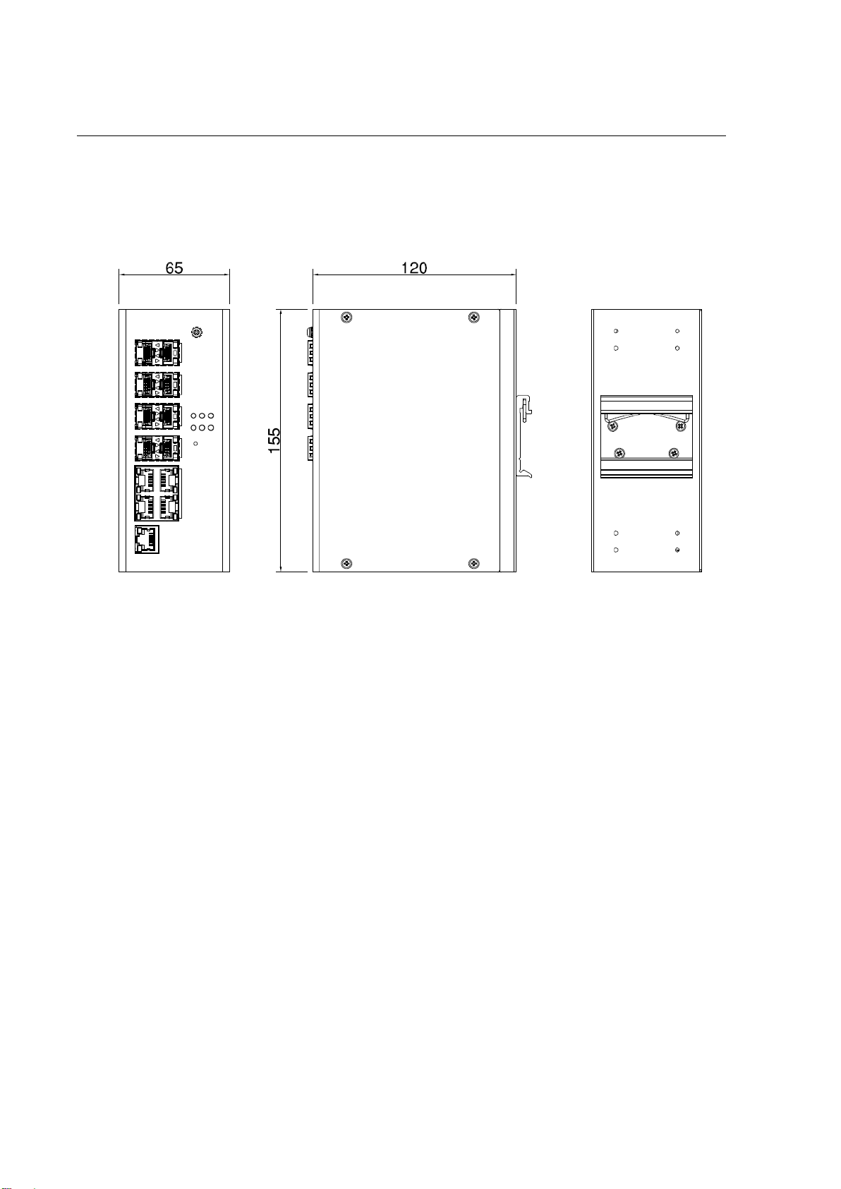
2.1HARDWARE DIMENSION..................................................................................................................................7
2.2WIRING THE POWER INPUTS............................................................................................................................9
2.3WIRING THE ALARM REL AY OUTPUT (DO)......................................................................................................10
2.4WIRING THE DIGITAL INPUT (DI) ....................................................................................................................11
2.5CONNECTING THE GROUDING SCREW ...........................................................................................................12
2.6 DIN RAIL MOUNTING .................................................................................................................................... 12
3. DEVICE INTERFACE MANAGEMENT .....................................................................................................................13
3.1 CONFIGURATION ..........................................................................................................................................22
3.1.1 SYSTEM .................................................................................................................................................22
3.1.2 GREEN ETHERNET.................................................................................................................................. 28
3.1.3 THERMAL PROTECTION .........................................................................................................................30
3.1.4 PORTS ...................................................................................................................................................31
3.1.5 SECURITY ..............................................................................................................................................33
3.1.6 AGGREGATION......................................................................................................................................63
3.1.7 LOOP PROTECTION................................................................................................................................67
3.1.8 SPANNING TREE ....................................................................................................................................68
3.1.9 IPMC ..................................................................................................................................................... 71
3.1.10 LLDP .................................................................................................................................................... 73
3.1.11 MAC TABLE .........................................................................................................................................75
3.1.12 VLAN ...................................................................................................................................................77
3.1.13 PRIVATE VLANS...................................................................................................................................82
3.1.14 QoS .....................................................................................................................................................83
3.1.14.1 QOS CLASSIFICATION .......................................................................................................................................84
3.1.14.2 POLICERS ........................................................................................................................................................84
3.1.14.3 SHAPERS.........................................................................................................................................................84
3.1.14.4 SCHEDULINGALGORITHM ................................................................................................................................84
3.1.14.5 WEIGHTED RANDOM EARLY DETECTION(WRED) ................................................................................................84
3.1.14.6 STORM POLICING ............................................................................................................................................85

4
3.1.14.7 INGRESS MAP..................................................................................................................................................85
3.1.14.8 EGRESS MAP ...................................................................................................................................................85
3.1.15 MIRRORING ...................................................................................................................................... 113
3.2 MONITOR ...................................................................................................................................................116
3.2.1 SYSTEM ............................................................................................................................................... 116
3.2.2 GREEN ETHERNET................................................................................................................................ 123
3.2.3 THERMAL PROTECTION ....................................................................................................................... 124
3.2.4 PORTS ................................................................................................................................................. 125
3.2.5 SECURITY ............................................................................................................................................130
3.2.6 AGGREGATION....................................................................................................................................131
3.2.7 LOOP PROTECTION.............................................................................................................................. 132
3.2.8 SPANNING TREE .................................................................................................................................. 133
3.2.9 IPMC ................................................................................................................................................... 137
3.2.10 LLDP ..................................................................................................................................................139
3.2.11 MAC ADDRESS .................................................................................................................................. 145
3.2.12 VLANS ...............................................................................................................................................146
3.3 DIAGNOSTICS.............................................................................................................................................. 149
3.3.1 PING (IPv4)..........................................................................................................................................149
3.3.2 TRACEROUTE (IPv4).............................................................................................................................151
3.3.3 VeryPHY..............................................................................................................................................153
3.4 MAINTANANCE ........................................................................................................................................... 153
3.4.1 RESTART.............................................................................................................................................. 154
3.4.2 FACTORY DEFAULT .............................................................................................................................. 154
3.4.3 SOFTWARE..........................................................................................................................................155
3.4.4 CONFIGURATION ................................................................................................................................156
3.5 FRONT PANEL.............................................................................................................................................. 159

5
1. INTRODUCTION
1.1 OVERVIEW
DS410F/DS410 series is designed for industrial environments requiring high quality fiber communication such as
industrial automation, road traffic control, etc. DS410F provides 10-port full-gigabit Ethernet including 6-port SFP,
2-port SFP/RJ45 combo and 2-port RJ45 (up to 8-port SFP); while DS410 provides 6-port RJ45, 2-port SFP/RJ45 combo
and 2-port SFP for multi-port Giga copper requirement. Full Gigabit capability and rugged industrial design ensures
system high performance and reliability in harsh environments, that has excellent heat dissipation design for
operating in -40~75oC environments. For convenient traffic control and zero packet loss data transmission,
DS410F/DS410 offer contemporary management and security functions. For the best traffic control, the switch
management side features have been utilized: LACP, VLAN, QinQ, QoS, IGMP snooping v2,and etc.
In order to uplink connection, the DS410F provides 2 RJ45/SFP Gigabit Ethernet combo ports that can prioritize
stream, such as video and also optimize VoIP. Gigabit Ethernet combo ports provides high speed uplink connection to
higher level backbone switches with Ring Network Redundancy technology ensures the reliability of high-quality
video transfer. High flexibility of cable types and distances for system integrators and DDM (Digital Diagnostic
Monitoring) type SFP transceivers also equipped the switch for diagnosing transmission problem through
maintenance and debugging of the signal quality.
WoMaster managed switch is designed to provide faster, secure, and more stable network. One advantage that
makes it a powerful switch is that it supports network redundancy protocols/technologies such as Rapid Spanning
Tree Protocol (RSTP).IEC 61000-6-2 / 61000-6-4 Heavy Industrial EMC certified design, rugged enclosure and
-40~75°C wide operating temperature range, - all these features guarantee stable performance of the switch for
surveillance data transmission under vibration and shock in rolling stocks, traffic control systems and other harsh
environments.
This managed switch also can be smartly configured by WoMaster advanced management utility, Web Browser,
SNMP, Telnet and RS-232 local console with its command like interface.
Excellent security features also provided, such as DHCP client, DHCP server with IP and MAC binding, 802.1X Port
Based Network Access Control, SSH for Telnet security, IP Access table, port security and many other security features.
All of these features in order to ensure the secure data communication.
The IP31-design aluminum case further strengthens the ability in harsh industrial environment. The event warning is
notified to the network administrator via e-mail, system log, or by relay output. The Industrial Managed Gigabit
Ethernet Switch has also passed CE/ FCC certifications to help ensure safe and reliable data transmission for industrial
applications.

6
1.2 MAJOR FEATURES
Below are the major features of DS410F Series Switch:
- 10-port Full Gigabit Ethernet, including 6 100/1000M SFP ports, 2 100/1000M SFP/RJ45 combo ports,
and 2 RJ45 ports
- High flexibility of cable types and distances for system integrators
- DDM function for high quality fiber connectivity monitoring
- 4K MAC address table
- Stores and forwards with non-blocking switch fabric
- Advanced Management Features: Flow Control, Port Trunk/802.3ad LACP, VLAN, Private VLAN, Shared VLAN,
Class of Service, Traffic Prioritize, Rate Control, Port Mirror, IGMP Snooping v2, Port classification, Port policing,
Port scheduler, Port shaping, QoS control list, WRED, Port Security, ACL, Loop Protection.
- Advanced Security System: IEEE 802.1X/RADIUS, Management IP, Management VLAN, SSL
- Redundancy Technology: Rapid Spanning Tree Protocol (RSTP)
- Various configuration paths, including Web GUI, CLI, and SNMP
- LLDP topology control
- 10~60V wide power range design with redundant
- power input NEMA-TS2 compliance for wayside traffic control assemblies
- Excellent heat dissipation design for operating in -40~75 ゚C environments
- High level EMC protection exceeding traffic control and heavy industrial standards’ requirements
- IEC 61000-6-2/4 Heavy Industrial Environment
- EN50121-4 railway trackside EMC Compliance
- IP31 ingress protection

7
2. HARDWARE INSTALLATION
This chapter introduces hardware, and contains information on installation and configuration procedures.
2.1 HARDWARE DIMENSION
Dimensions of DS410F/DS410: 65 x 155 x 120 (W x H x D) / without DIN Rail Clip

8
Front Panel Layout
Below is the front panel from DS410F Series switches, for DS410F is included 6 ports 100/1000M SFP, 2 ports
100/1000M SFP/RJ45 Combo, 2 ports 10/100/1000M RJ45, and for DS410, it is included 6 ports 10/100/1000M SFP, 2
ports 100/1000M SFP/RJ45 Combo, 2 ports 100/1000M RJ45, System LED, USB for configuration/firmware
management, RJ-45 diagnostic console, 2 x 4-pin terminal block connector (4 pin for power inputs, 2 pin for digital
input and 2 pin for alarm relay output) and 1 chassis grounding screw. On the rear side of switch there is DIN rail clip
attached.
DS410F/DS410

9
2.2 WIRING THE POWER INPUTS
Power Input port in the switch provides 2 sets of power input connections (P1 and P2) on the terminal block. x
On the picture below is the power connector.
Wiring the Power Input
1. Insert the positive and negative wires into the V+ and V- contact on the terminal block connector.
2. Tighten the wire-clamp screws to prevent the power wires from being loosened.
3. Connect the power wires to suitable AC/DC Switching type power supply. The input DC voltage should be in
the range of 10VDC to DC 60V DC.
WARNING: T
urn off AC power input source before connecting the Power to the terminal block
connectors, for safety purpose. Don not turn-on the source of AC/DC power before all of the
connections were well established.

10
2.3 WIRING THE ALARM RELAY OUTPUT (DO)
The relay output contacts are located on the front panel of the switch. The relay output consists of the 2-pin
terminal block connector that used to detect user-configured events. The two wires attached to the fault contacts
form a close circuit when a user-configured event is triggered. If a user-configured event does not occur, the fault
circuit remains opened. The fault conditions such as power failure, Ethernet port link break or other pre-defined
events which can be configured in the switch. Screw the DO wire tightly after digital output wire is connected.
NOTE: The relay contact only supports 0.5 A current, DC 24V. Do not apply voltage and current higher
than the specifications.
Este manual sirve para los siguientes modelos
1
Tabla de contenidos
Otros manuales de Cambiar de WoMaster

WoMaster
WoMaster DP612 Manual de usuario

WoMaster
WoMaster DS108 Series Manual de usuario

WoMaster
WoMaster DP310 Manual de usuario

WoMaster
WoMaster DP208 Manual de usuario

WoMaster
WoMaster DS105 Manual de usuario

WoMaster
WoMaster RS428 Manual de usuario

WoMaster
WoMaster MP614 Series Manual de usuario

WoMaster
WoMaster RP428 Manual de usuario


