Well Bubbler 10-120 Manual

THE WELL BUBBLER
WWW.WELLBUBBLER.COM
INSTALLATION AND
CONFIGURATION
MANUAL
MODEL 10-120
MODEL 10-300
DRAWN BY: A. BUGROV DATE: 02.20.2021 PAGE: 1

THE WELL BUBBLER
WWW.WELLBUBBLER.COM
INSTALLATION STEP 1
The Well Bubbler 10-120 AND 10-300 re designed for mounting on 1-5/8” ch nnel
strut, m nuf ctured by UniStrut nd U-Line. Begin the sensor inst ll tion by mounting
the strut ne r the well he d – either on tripod s shown below, or on b ckbo rd.
Orient the open f ce of the strut due South for inst ll tions in the Northern Hemisphere,
nd due North otherwise.
DRAWN BY: A. BUGROV DATE: 02.20.2021 PAGE: 2

THE WELL BUBBLER
WWW.WELLBUBBLER.COM
INSTALLATION STEP 2
Inst ll the Well Bubbler on the ch nnel strut using the 1/2-13 f steners included with
the unit. Tighten the f stener using 3/4 wrench; note th t the entire weight of the
unit is supported by this f stener – torque it ppropri tely.
DRAWN BY: A. BUGROV DATE: 02.20.2021 PAGE: 3

THE WELL BUBBLER
WWW.WELLBUBBLER.COM
INSTALLATION STEP 3
Insert the 1/4” OD tubing into the push-to-connect fitting s shown below.
Depress the green push ring, nd pull the tubing, to remove it if necess ry.
DRAWN BY: A. BUGROV DATE: 02.20.2021 PAGE: 4

THE WELL BUBBLER
WWW.WELLBUBBLER.COM
INSTALLATION STEP 4
Inst ll the fuse provided with the Well Bubbler into the fuse holder, s shown below.
Push the fuse holder in, nd rot te to the right, to eng ge the fuse. Do not substitute
this fuse with ny other type, or r ting – sp re fuses re shipped with the sensor.
The displ y should now ctiv te; note th t the Well Bubbler m y begin oper ting once
the fuse is inst lled. Refer to the following steps for ctiv ting, or tempor rily
de ctiv ting, the unit.
The fuse should be left inst lled whenever the Well Bubbler is mounted outdoors,
llowing the b tteries to m int in ch rge.
DRAWN BY: A. BUGROV DATE: 02.20.2021 PAGE: 5

THE WELL BUBBLER
WWW.WELLBUBBLER.COM
DIGITAL DISPLAY
The Well Bubbler includes digit l displ y used to view well level, flow r te, pump
disch rge pressure nd pump current. The s me displ y is used to st rt, or stop,
utom tic me surement nd to configure the Well Bubbler. The displ y includes three
buttons: center round button, the right rect ngul r button, nd the left rect ngul r
button.
Center (round) button: press this button once to turn on the b ck light; this fe ture is
useful in low light, nd will turn off utom tic lly to conserve energy. Press the center
button g in to move, or toggle, between different menus.
Right: press this button to incre se setting, such s the displ y contr st
Left: press this button to decre se, or lower, setting
Most menu items re used to configure the Well Bubbler, nd re ccessed through
speci l button sequence - this prevents un uthorized ccess to import nt settings.
Press, nd continue to hold, the center round button, then press nd hold the right
button. After five seconds, the configur tion menus become v il ble tempor rily.
DRAWN BY: A. BUGROV DATE: 02.20.2021 PAGE: 6

THE WELL BUBBLER
WWW.WELLBUBBLER.COM
DISPLAY: MAIN MENU
The m in menu is shown once the fuse is inst lled; it cont ins the following items:
Well level: the l st known v lue s me sured by the unit, with fully purged irline
Testing: the current pressure in the irline, in PSI, nd the ssoci ted well level
St t: the st tus indic tor shows the oper ting mode of the unit (Testing, W iting, etc.)
t: the timer showing the dur tion of the current test, nd the period between successive
test runs
Vb t: The intern l b ttery volt ge, nomin lly between 11.5V nd 14.4V
T: The intern l temper ture of the unit, in degrees F; shown for reference only
DRAWN BY: A. BUGROV DATE: 02.20.2021 PAGE: 7

THE WELL BUBBLER
WWW.WELLBUBBLER.COM
DISPLAY: CONTRAST ADJUSTMENT
The Bubbler djusts the displ y contr st utom tic lly, b sed on the displ y
temper ture, to improve visibility in bright sunlight. This menu c n be used to
override the utom tic djustment.
DRAWN BY: A. BUGROV DATE: 02.20.2021 PAGE: 8

THE WELL BUBBLER
WWW.WELLBUBBLER.COM
DISPLAY: WELL LEVEL
This menu shows the l st me sured well level, with fully purged irline. Note th t
this me surement is m de intermittently – for ex mple, every five or fifteen minutes,
nd only the l st known v lue is shown on the displ y.
The displ yed v lue m y be slightly different th n the ctu l “current” well
level, depending on the well ctivity nd s mpling period.
DRAWN BY: A. BUGROV DATE: 02.20.2021 PAGE: 9
THE WELL BUBBLER
WWW.WELLBUBBLER.COM
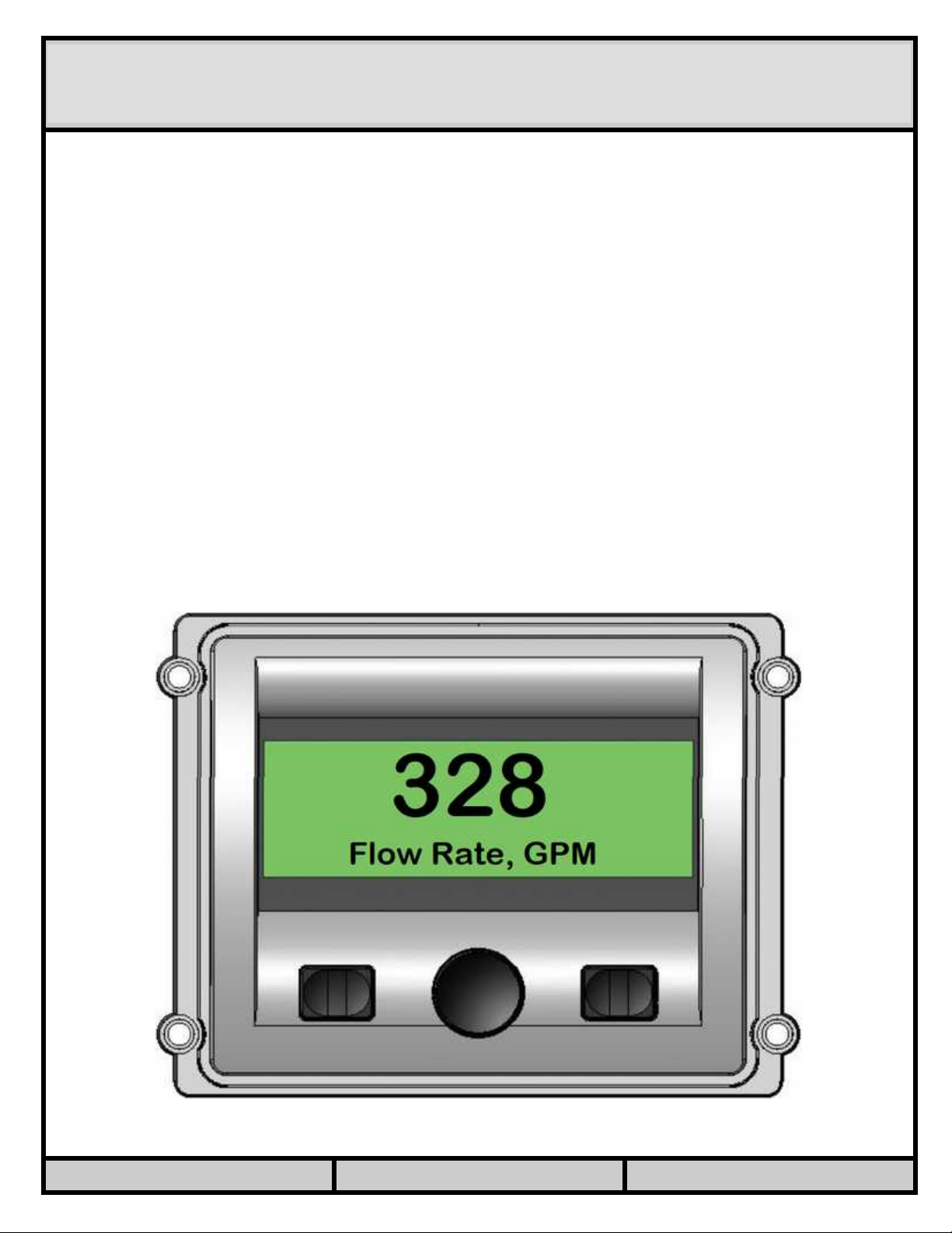
DISPLAY: FLOW RATE
This menu shows the l st me sured flow r te v lue. A 4-20mA or pulse-type flow
meter must be inst lled, wired to the Well Bubbler, nd configured correctly, to
me sure flow r te.
If pulse-type flow meter is used, the me surement is n ver ge c lcul ted over
sever l seconds, nd upd ted continuously. This me ns th t the displ yed v lue
m y be different from the one shown on the flow meter displ y, especi lly if the
flow r te is v ri ble.
Note lso th t the displ yed v lue m y be different th t the one recorded in the
d t log, or reported on the d shbo rd – those v lues re ver ged over the entire
me surement period of, for ex mple, five or fifteen minutes.
If 4-20mA flow meter is used, the displ yed v lue is the inst nt neous re ding
t ken during the l st well level s mple, nd will not be upd ted until the next
s mple is t ken – for ex mple, once every five or fifteen minutes. A new, upd ted
flow r te v lue will be displ yed if the center button is pressed repe tedly to
re ch this menu.
DRAWN BY: A. BUGROV DATE: 02.20.2021 PAGE: 10
Este manual sirve para los siguientes modelos
1
Tabla de contenidos
Manuales populares de Calentador de otras marcas


Empire Heating Systems
Empire Heating Systems WCC65 Manual de usuario

Wetekom
Wetekom 92 86 43 Manual de usuario

Desa
Desa SPC170-F Manual de usuario

Watlow
Watlow Watrod Electric Tubular Heaters Manual de usuario

Haverland
Haverland ECO-DRY GPS Series Manual de lista de piezas

Stelpro
Stelpro ASILVC2060 Series Manual de usuario