Webasto MultiControl Manual de usuario

Installation Instructions
Control element
MultiControl | SmartControl | UniBox
English
MultiControl
+HDWLQJ
+HDWLQJ
SmartControl

MultiControl | SmartControl | UniBox 2
Table of Contents
1 About This Document 3
1.1 Purpose of the document 3
1.2 Documents supplied 3
1.3 Use of this document 3
1.4 Use of symbols and highlighting 3
1.5 Liability waiver 3
2 Safety 4
2.1 Intended use 4
2.2 Qualification of the installation personnel 4
2.3 Regulations and statutory provisions 4
2.4 Safety instructions 4
3 Device Description 5
3.1 Delivery scope 5
3.2 Identification plate 5
3.3 Description of Functions 5
3.4 Device versions 5
3.5 Use 5
4 Installation of the Control Element 6
4.1 Recommendations for installation 6
4.2 Requirements for the installation location 6
4.3 Install control element 6
4.4 Optional: Install UniBox 7
5 Initial Start-up 9
5.1 Recommendations for initial start-up 9
5.2 Put the device into operation 9
5.3 Select heater 9
6 Technician Mode 11
6.1 Description of Functions 11
6.2 Connection of the diagnostic adapter 11
6.3 Select the Service menu 11
7 Fault Remedy 12
7.1 Error code 12
8 Technical Data 14
9 Annex 15
9.1 Connections 15
9.2 Technician Mode 16
9.3 Schematic Overview of Service Menu 19

MultiControl | SmartControl | UniBox 3
1 About This Document
1.1 Purpose of the document
The installation instructions form part of the device and contain
information for the correct and safe installation.
1.2 Documents supplied
All documents can be found on the enclosed DVD and can also be
downloaded from http://dealers.webasto.com.
The following documents are supplied with the device in printed
form:
■Quick-start guide
1.3 Use of this document
If necessary, print out these installation instructions.
Read these installation instructions before installing the device.
Read the instruction manual before operating the device.
1.4 Use of symbols and highlighting
WARNING
Type and source of danger
Effect: Failure to follow the instructions can lead to
serious or even fatal injuries
Action to protect yourself from the danger.
CAUTION!
Type and source of danger
Effect: Failure to follow the instructions can lead to
minor injuries
Action to protect yourself from the danger.
CAUTION
Type and source of material damage
Effect: Failure to follow the instructions can lead to
material damage
Action to avoid material damage.
Further information can be found in the following
documents:
■...
■...
Reference to a special technical feature.
Highlighting Explanation
3Precondition for the subsequent instruction
Instruction
1.5 Liability waiver
Webasto assumes no liability for faults and damage resulting from
a failure to follow the installation instructions and instruction
manual and the tips contained therein.
This liability waiver applies in particular to:
■Installation by unqualified personnel
■Improper use
■Repairs not carried out by a Webasto service workshop
■Use of non-original parts
■Modification of the device without the approval of Webasto
https://webasto-russia.ru

MultiControl | SmartControl | UniBox 4
2 Safety
2.1 Intended use
The control element serves to control the heater.
2.2 Qualification of the installation per-
sonnel
The installation personnel must have the following qualifications:
■Successful completion of the Webasto training
■Corresponding qualification for working on technical systems
2.3 Regulations and statutory
provisions
Observe the important information in the "Quick-start guide"
leaflet.
2.4 Safety instructions
Safety instructions for installation
Hazard of electric shock from live components
Before installation, disconnect the vehicle from the power sup-
ply.
Pay attention to proper earthing of the electrical system.
Observe the legal provisions.
Observe the information on the identification plate.
Danger of cuts from sharp edges
Fit chafers to sharp edges.
Safety instructions for operation
Risk of explosion in areas with flammable vapours, flammable
dusts and
hazardous goods (e.g. petrol stations, tank installations, fuel
stores, coal stores, wood stores or grain stores)
Do not switch on or operate the heater.
Risk of poisoning and suffocation caused by exhaust fumes in
enclosed areas without exhaust extraction system
Do not switch on or operate the heater.
Avoid material damage
Risk of short-circuit resulting from damage to cables due to sharp
edges
Fit chafers to sharp edges.

MultiControl | SmartControl | UniBox 5
3 Device Description
3.1 Delivery scope
■MultiControl / SmartControl
■Double-sided adhesive pad
■Optional: Holder for MultiControl / SmartControl
■Optional: UniBox
■Optional: Holder for UniBox
3.2 Identification plate
The identification plate is located on the rear side of the control
element.
3.3 Description of Functions
Control element
The MultiControl and SmartControl control elements are used to
control Webasto heaters.
The additional installation of the UniBox (optional) may be neces-
sary, depending on the installed heater and the application.
Heating
Fig. 01: MultiControl / SmartControl control elements
1 Submenu designation
2 Submenu symbol
3 Activated time setting
4 Time
5 Quick-start button
6 Control knob
UniBox
The UniBox allows heaters not compatible with the W bus to
also be operated with the MultiControl and SmartControl control
elements. Furthermore, the UniBox provides further inputs and
outputs which extend the scope of functions.
Communication between UniBox and control element is via the
W bus. The UniBox is automatically configured after selecting the
heater at the control element.
The UniBox is installed in an area of the vehicle not visible to the
customer.
3.4 Device versions
The control element is available in two versions:
■SmartControl: Control element with black frame without timer
function.
■MultiControl: Control element with silver frame and with timer
function.
The heaters and default settings supported depend
on the version of the control element used.
3.5 Use
The heaters for which the control element may be used can be
found under: http://dealers.webasto.com

MultiControl | SmartControl | UniBox 6
4 Installation of the Control Element
4.1 Recommendations for installation
CAUTION!
Electric shock if live parts are touched
Minor burns
Isolate the vehicle before installation (vehicle
initialisation may be lost).
CAUTION!
Risk of fire due to incorrect installation
Risk of burns
Observe the additional regulations if installing the
heater in vehicles for hazardous goods transport.
Observe the information on the identification
plate.
CAUTION!
Risk of fire caused by drilling into lines or
cables
Risk of burns
Lay lines and cables behind the installation sur-
face out of the drilling area.
CAUTION!
Risk of injuries caused by touching sharp
edges
Skin abrasions, cuts
Use protective gloves during installation.
4.2 Requirements for the installation loca-
tion
The installation location must satisfy the following requirements:
3Vehicle interior
3Easily accessible
3Clear visibility
3Clean, dry and grease-free
3Protected from dampness and moisture
3Protected from heat, not directly in the hot air current
3Adequate free space behind the installation location
4.3 Install control element
Installation with adhesive pads
123
Fig. 02: Install control element with adhesive pads
1 Installation location
2 Adhesive pads (adhesive on both sides)
3 Control element
Determine the installation location.
When determining the location, pay attention to
the length of the control element cable.
Determine the location for the leadthrough of the control ele-
ment wiring harness.
Lay the control element wiring harness through from the front.
3The rear side of the control element is clean, dry and free from
dust or grease.
Attach the adhesive pads to the control element.
Attach the control element to the selected installation location.

MultiControl | SmartControl | UniBox 7
Optional installation with holder
12 43
Fig. 03: Install control element with holder
1 Installation location
2 Holder
3 Screws
4 Control element
Determine the installation location.
Determine the location for the leadthrough of the control ele-
ment wiring harness.
Install the holder using the screws supplied.
Lay the control element wiring harness through from the front.
Clip the control element into the holder.
Observe the statutory regulations when installing
in cars.
1
2
Fig. 04: Connection example control element (1) with heater (2)
4.4 Optional: Install UniBox
Fig. 05: Optional: Install UniBox with holder
Determine the installation location.
Install the device in an area of the vehicle not visible
to the customer.
Install the holder using the screws supplied.
Determine the routing of the wiring harness of the UniBox.
Clip the UniBox into the holder.

MultiControl | SmartControl | UniBox 8
12
3 4
Fig. 06: Connection example – UniBox (1), control element (2), heater (3)
and vehicle wiring harness (4)

MultiControl | SmartControl | UniBox 9
5 Initial Start-up
5.1 Recommendations for initial start-up
WARNING
Inhalation of toxic gases in enclosed areas
Risk of poisoning and suffocation
Never use the heater in enclosed areas such as
garages or workshops without exhaust extraction
system, even in the case of programmed heating.
In workshops with exhaust extraction system,
ensure that the exhaust extraction system is
functioning.
5.2 Put the device into operation
3Heater is correctly installed.
3Control element is correctly installed.
Connect the vehicle power supply.
5.3 Select heater
For initial start-up
When the control element is connected for the first
time, a message about the missing setting/configu-
ration of the heater is displayed.
Fig. 07: Symbol "Missing configuration"
Press the control knob and the quick-start knob simultaneously
for 3 seconds.
+HDWHU
Fig. 08: Menu element "Heater"
Select the desired heater.
Press the control knob.
'D\
Fig. 09: Menu element "Day"
Select the current day.
Press the control knob.
Fig. 10: Menu element "Time"
Select the current time.
For manual reset
A reset returns all the settings and timer pro-
grammes in the control element to the basic set-
tings or to the default values set by the technician.
At a reset, the language setting is reset to English.
In the main menu, select the symbol "Settings" .
Settings
Fig. 11: Menu element "Settings"
Press the control knob.
Select menu element "Reset".
Reset
Settings
Fig. 12: Menu element "Reset"
Press the control knob.
Reset
Settings
Fig. 13: Menu element "Confirm reset"
To confirm the menu selection, press the control knob again.
3The control element is restarted.
During the restart of the control element (the starting mask is
displayed for 1.5 seconds), press the control knob and quick-
start knob simultaneously for 3 seconds.

MultiControl | SmartControl | UniBox 10
+HDWHU
Fig. 14: Menu element "Heater"
Select the desired heater.
Press the control knob.
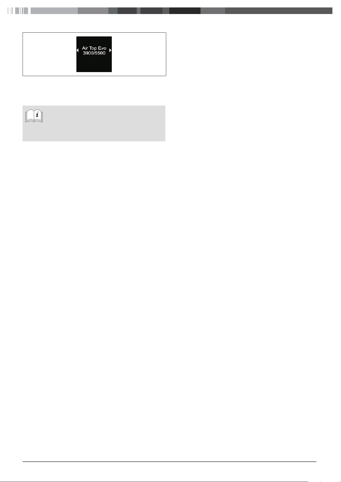
The correct selection for the corresponding heater
can be found in the workshop manual for the
heater.
Otros manuales para MultiControl
2
Este manual sirve para los siguientes modelos
2
Tabla de contenidos
Otros manuales de Unidad de control de Webasto
Manuales populares de Unidad de control de otras marcas

Festo
Festo Compact Performance CP-FB6-E Manual de lista de piezas

Elo TouchSystems
Elo TouchSystems DMS-SA19P-EXTME Manual de usuario

JS Automation
JS Automation MPC3034A Manual de usuario

JAUDT
JAUDT SW GII 6406 Series Guía rápida

Spektrum
Spektrum Air Module System Manual de usuario

BOC Edwards
BOC Edwards Q Series Manual de usuario