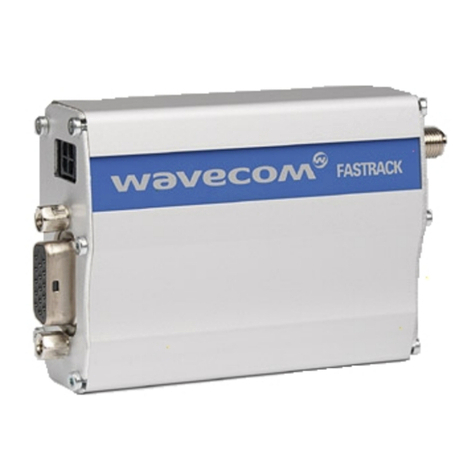
Wavecom GX64 Instrucciones de instalación y funcionamiento

Gx64 APPLICATION NOTE
Power Management
Reference:
W
I_DEV_Gx64_APN_007
Version: 001
Date: 2007/01/31

Trademarks
®, WAVECOM®, WISMO®, Open AT®, Wireless CPU®, Wireless Microprocessor®and certain
other trademarks and logos appearing on this document, are filed or registered trademarks
of Wavecom S.A. in France or in other countries. All other company and/or product names
mentioned may be filed or registered trademarks of their respective owners.
Copyright
This manual is copyrighted by WAVECOM with all rights reserved. No part of this manual may
be reproduced in any form without the prior written permission of WAVECOM.
No patent liability is assumed with respect to the use of the information contained herein.
No Warranty
WAVECOM publishes this manual without making any warranty as to the content contained
herein. Further Wavecom Inc reserves the right to make modifications, additions and
deletions to this manual due to typographical errors, inaccurate information, or
improvements to programs and/or equipment at any time and without notice. Such changes
will, nevertheless be incorporated into new editions of this manual.
Gx64 APPLICATION NOTE This document is the sole and exclusive property of WAVECOM. Not to be distributed or divulged without prior written agreement.
Ce document est la propriété exclusive de WAVECOM. Il ne peut être communiqué ou divulgué à des tiers sans son autorisation préalable
Power Management
Page: 2/30

Table of Contents
1Introduction ............................................................................................ 5
1.1 ABBREVIATIONS ............................................................................................................ 5
1.2 NOTATION.................................................................................................................... 6
1.3 ACKNOWLEDGEMENTS .................................................................................................. 6
2Block Diagrams ....................................................................................... 7
2.1 SYSTEM POWER MANAGEMENT BLOCK DIAGRAM ........................................................... 7
2.2 POWER MANAGEMENT BLOCK DIAGRAM........................................................................ 8
2.2.1 GS64.................................................................................................................. 8
2.2.2 GR64001 ........................................................................................................... 9
2.2.3 GR64002 ......................................................................................................... 10
3Implementation Recommendations ....................................................... 11
3.1 APPLYING POWER ON VCC........................................................................................... 11
3.2 POWER STATE CONTROL OF THE WIRELESS CPU........................................................... 12
3.2.1 ON/OFF ........................................................................................................... 13
3.2.2 INTERNAL CHGDET........................................................................................... 14
3.2.3 EXTERNAL PON_H............................................................................................. 14
3.2.4 ALARM............................................................................................................. 15
3.2.5 AT+CFUN ........................................................................................................ 16
3.2.6 AT*E2RESET ..................................................................................................... 16
3.3 HOW TO LOWER POWER CONSUMPTION ...................................................................... 16
3.4 CHARGING.................................................................................................................. 17
3.5 HOW TO USE VREF ...................................................................................................... 17
3.5.1 VREF AS OUTPUT IN GS64 AND GR64001 ......................................................... 17
3.5.2 VREF AS INPUT IN GR64002.............................................................................. 18
3.6 MONITOR “POWER ON” STATE ..................................................................................... 19
3.6.1 GS64 AND GR64001 HW-DETECTION ............................................................... 19
3.6.2 GR64002 HW-DETECTION................................................................................ 20
Gx64 APPLICATION NOTE This document is the sole and exclusive property of WAVECOM. Not to be distributed or divulged without prior written agreement.
Ce document est la propriété exclusive de WAVECOM. Il ne peut être communiqué ou divulgué à des tiers sans son autorisation préalable
Power Management
Page: 3/30

3.7 VRTC AND ALARM ...................................................................................................... 22
3.7.1 USING ALARM AS PERIODIC POWER ON ............................................................. 22
4Reference Designs ................................................................................ 24
4.1 DISCLAIMER................................................................................................................ 24
4.2 DC/DC POWER SUPPLY ................................................................................................ 24
4.2.1 BILL OF MATERIAL ............................................................................................ 24
4.3 AC/DC POWER SUPPLY ................................................................................................ 25
4.3.1 SPECIFICATIONS ............................................................................................... 25
4.3.2 DESIGN SUMMARY............................................................................................ 25
4.3.3 BILL OF MATERIAL ............................................................................................ 27
Appendix A................................................................................................. 28
Appendix B ................................................................................................. 29
Table of Figures
Figure 1: System Block Diagram ........................................................................................... 7
Figure 2: GS64 Power Management Block Diagram ............................................................... 9
Figure 3: GR64001 Power Management Block Diagram......................................................... 9
Figure 4: GR64002 Power Management Block Diagram....................................................... 10
Figure 5: GR/GS64 HW On/Off Sequence Logic................................................................... 12
Figure 6: Power Management State Diagram....................................................................... 13
Figure 7: Interface circuit implementation for GS64............................................................ 18
Figure 8: Typical VREF level translation implementation in a GR64002 ............................... 19
Figure 9: GR64002 Power State detection........................................................................... 20
Figure 10: ALARM application example .............................................................................. 22
Gx64 APPLICATION NOTE This document is the sole and exclusive property of WAVECOM. Not to be distributed or divulged without prior written agreement.
Ce document est la propriété exclusive de WAVECOM. Il ne peut être communiqué ou divulgué à des tiers sans son autorisation préalable
Power Management
Page: 4/30

1Introduction
This document describes how to apply power, control power states (On/Off), and give
other hints on how to optimise the Wireless CPU implementation.
1.1 Abbreviations
Abbreviation Description
CSD Circuit Switched Data
CPS Charging Power Supply. Indicates the voltage and current limited
supply connected to CHG_IN when battery charging is used.
DRX
Discontinuous Receive. This indicates how often the Wireless CPU
has to wake up and look for a page. The mode can be between 2
and 9 and is determined by the base station.
FAE Field Application Engineer
PSC Power Supply and Indicator
PSI Power State Change signal
RTC Real-Time-Clock residing in the Wireless CPU.
TP Temperature Protection. Built-in temperature protection of the
Power Management ASIC.
UVLD Under Voltage Level Detect. Voltage level detection of VCC.
Gx64 APPLICATION NOTE This document is the sole and exclusive property of WAVECOM. Not to be distributed or divulged without prior written agreement.
Ce document est la propriété exclusive de WAVECOM. Il ne peut être communiqué ou divulgué à des tiers sans son autorisation préalable
Power Management
Page: 5/30

1.2 Notation
The following symbols and admonition notation are used to draw the reader’s
attention to notable or crucially-important information.
Note
Draws the readers attention to pertinent, useful or interesting
information
Tip
Provides advice, suggestions, guidance or recommendations which
augment the formal text
NOTE
TIP
Caution
Cautionary information must be heeded, it draws the readers attention
to the need for understanding, care or watchfulness in relation to the
information provided
CAUTION
Warning
Notes marked warning must be heeded, they alert readers to
precautionary measures, risks, hazards or safety information which
directly effects equipment function, warranty or personnel safety
!
WARNING
Danger
This information must be heeded, it identifies information and
cautionary behaviour that otherwise ignored could result in
catastrophic equipment failure, bodily injury or death
DANGE
R
1.3 Acknowledgements
Parts of this document, including text passages, tables, and illustrations, are
reproduced from copyright information by kind permission of Agere Systems Inc.
Gx64 APPLICATION NOTE This document is the sole and exclusive property of WAVECOM. Not to be distributed or divulged without prior written agreement.
Ce document est la propriété exclusive de WAVECOM. Il ne peut être communiqué ou divulgué à des tiers sans son autorisation préalable
Power Management
Page: 6/30

2Block Diagrams
2.1 System Power Management Block Diagram
The GR/GS64 Wireless CPUs have a number of signals in the system connector that
affect the power state. The signals in Figure 1 show the signals for all types and
variants of the GR/GS64 family of Wireless CPUs.
Table 1 below lists what features are available for the different types and variants.
Figure 1: System Block Diagram
VREF is implemented differently in the two different GR64 variants. VREF is either an
input or an output and are obviously mutually exclusive. Figure 1 only shows VREF as
an output, which is the way it is implemented in the GR64001 and GS64.
The signal can be divided into two types:
•Power Supplies and indicators (PSI)
•Power state change signals (PSC)
The CHG_IN signal is both a PSI and a PSC.
Gx64 APPLICATION NOTE This document is the sole and exclusive property of WAVECOM. Not to be distributed or divulged without prior written agreement.
Ce document est la propriété exclusive de WAVECOM. Il ne peut être communiqué ou divulgué à des tiers sans son autorisation préalable
Power Management
Page: 7/30

Table 1: Type / Variant Configuration
GR64001 GR64002 GS64
Feature Type
Pin(s) Pin(s) Pin(s)
VCC PSI √1,3,5,7,9 √1,3,5,7,9 √2,4,6,8,10,12
CHG_IN PSI/PSC √11 √11 √13
VUSB PSI √49 √34
VREF as input √
VREF as output PSI √34 34 √65
VRTC PSI √25 √25 √31
ALARM PSC √50 √32
PON_H PSC √21
ON/OFF PSC √14 √14 √33
2.2 Power Management Block Diagram
This section describes the individual implementations in the three different designs;
GS64, GR64001, and GR64002.
Detailed information on the PSC-implementation can be found in 3.2 below
2.2.1 GS64
The GS64 implementation uses all PSC-options listed in Table 1. If a signal is not
used it should be left floating.
The “PM ON/OFF Sequence Logic” block diagram can be found in Figure 5.
Gx64 APPLICATION NOTE This document is the sole and exclusive property of WAVECOM. Not to be distributed or divulged without prior written agreement.
Ce document est la propriété exclusive de WAVECOM. Il ne peut être communiqué ou divulgué à des tiers sans son autorisation préalable
Power Management
Page: 8/30

Figure 2: GS64 Power Management Block Diagram
2.2.2 GR64001
This variant of GR64 only implements two PSC-options, ON/OFF and CHG_IN.
Figure 3: GR64001 Power Management Block Diagram
The “PM ON/OFF Sequence Logic” block diagram can be found in Figure 5.
Gx64 APPLICATION NOTE This document is the sole and exclusive property of WAVECOM. Not to be distributed or divulged without prior written agreement.
Ce document est la propriété exclusive de WAVECOM. Il ne peut être communiqué ou divulgué à des tiers sans son autorisation préalable
Power Management
Page: 9/30

2.2.3 GR64002
This variant of GR64 implements all four PSC-options, ON/OFF, PON_H, ALARM and
CHG_IN.
Figure 4: GR64002 Power Management Block Diagram
The “PM ON/OFF Sequence Logic” block diagram can be found in Figure 5.
Gx64 APPLICATION NOTE This document is the sole and exclusive property of WAVECOM. Not to be distributed or divulged without prior written agreement.
Ce document est la propriété exclusive de WAVECOM. Il ne peut être communiqué ou divulgué à des tiers sans son autorisation préalable
Power Management
Page: 10/30
Otros manuales para GX64
3
Tabla de contenidos
Otros manuales de Hardware de computadora de Wavecom
Manuales populares de Hardware de computadora de otras marcas

EMC2
EMC2 VNX Series Manual del propietario

Panasonic
Panasonic DV0PM20105 Manual de usuario

Mitsubishi Electric
Mitsubishi Electric Q81BD-J61BT11 Manual de usuario

Gigabyte
Gigabyte B660M DS3H AX DDR4 Manual de usuario

Raidon
Raidon iT2300 Manual de usuario

National Instruments
National Instruments PXI-8186 Manual de usuario