Wave Central PAINT TX Manual de usuario

1
AXTX1–BroadcastCameraControl
PaintSystemGuide
RCP‐TX‐IDU
CAMERATALLYINTERFACEUNITAXTX1CameraTXTX‐ODU
Wave Central LLC
99 Garden Parkway, Suite C., Carlisle, PA
+1 888 736 9283 www.wave-central.com

2
Overview
The Camera Control Unit Paint System comprises of three main elements: The Remote
Control PAINT TX Indoor Unit (RCP-TX-IDU) the Camera Tally Interface and the
Transmitter Outdoor Unit (TX ODU). It is simple to configure, as per the diagram to
provide camera control for up to 4 cameras on a single UHF channel. The radio channel
is programmable from 403 to 474 MHz via the daylight readable display, using the
navigation buttons provided. The fourth component is the AXTX1 Broadcast Camera
Transmitter with Camera Paint Data Receiver.
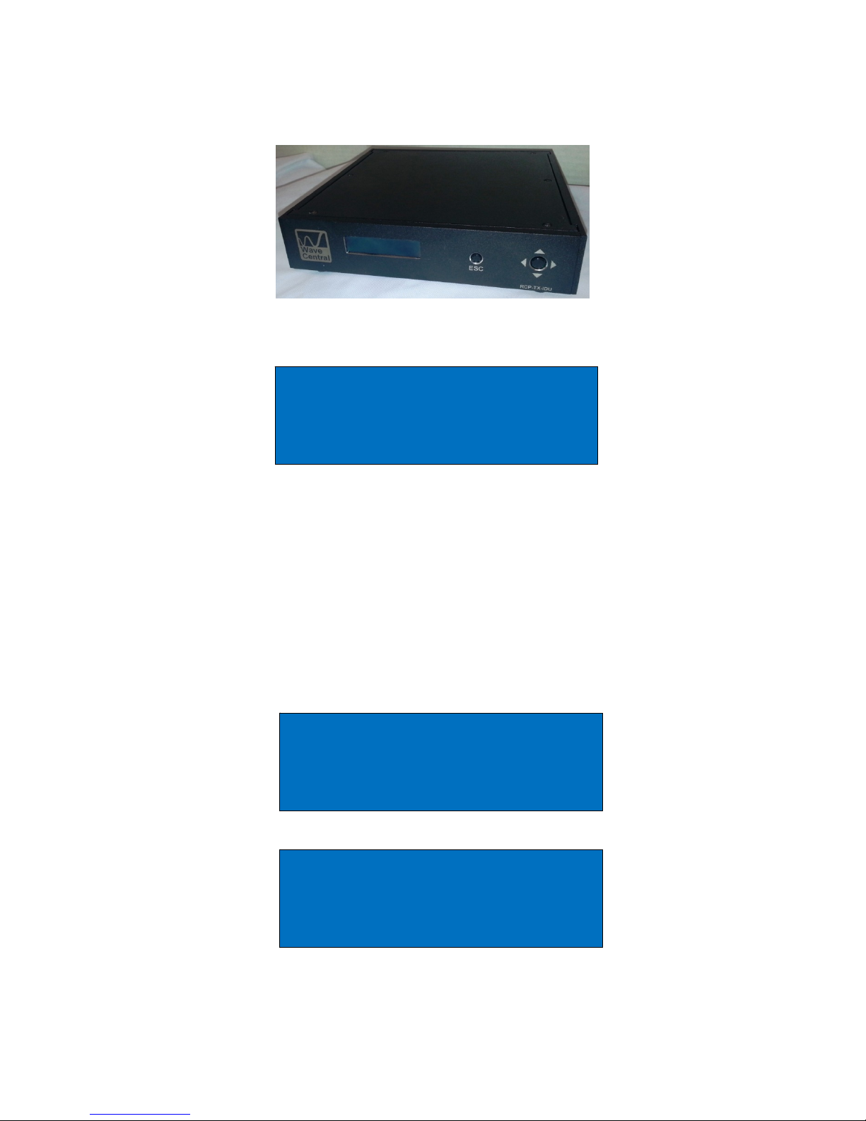
Figure 1. RCP-TX-IDU
Figure 2. Camera Tally Interface Unit
Figure 3. TX ODU

3
1. Indoor Unit
1.1 Connections
The RCP-TX-IDU should be situated in a suitable place to gain access to the front panel
when required. The RCP-TX-IDU should be connected to the TX ODU using Cat 5 or 6
data cable (not supplied). There are four DB-9 pin female ports on the rear panel; they
are labelled CCU1 to CCU4. The port number relates to the Camera RCP ID that will be
connected to the RCP-TX-IDU. Example; a panel connected to port number 1 will have
a system ID of 1. Up to 4 panels can be connected at any one time to control a
maximum of 4 independent cameras. In the case of the Sony control panel, the ID/Port
number will be indicated on the panel in the Tally Display area.
Camera tally are interfaced via the camera tally interface. Connectivity between the
camera tally interface and the RCP-TX-IDU are Cat 5 or 6 ethernet cable connection the
Red and Green Tally respectively. The video switch tally control (contact closure) is
connected to Red and Black ‘Push Terminal’ tabs on the Tally interface unit.
AC power is applied to the RCP-TX-IDU.
Figure 4. Three Camera Control Unit Paint components
Note: Not pictured is the Fourth component of the system is the AXTX1 Broadcast
Camera Transmitter with Camera Paint Data Receiver.

4
1.2 Status Display
With the ODU connected the power should be applied to the unit, 12VDC via the 4 pin
XLR connector, utilizing the standard pin configuration. On power up the CP Logo,
should be seen on the splash screen followed by the home status as shown below.
Outlined is the status of each port connection, reported Connected or Disconnected.
The display is used in conjunction with the navigation buttons to interrogate the unit
and read the frequency and power output of the ODU. Notification of a Tally to that
port is indicated by R for RED Tally and G for GREEN tally
1.3 Manufacturing Status
If the NAV button is pressed once the Camera manufacture menu can be seen. By tipping the
NAV button up and down different manufactures can be chosen and if the relevant license has
been obtained, selected. When the desired manufacturer has been reached, the NAV button is
pressed once to select. The display will revert back to the Manufacture Status
NOTE: The power must be cycled before the selection will be actioned by the internal
processor.
1: Connected RG
2: Disconnected
3: Disconnected
4: Disconnected
Main Menu
Camera Manufacture
Camera Manufacture
Sony
5
1.4 Radio Status
Figure 5. RCP-TX-IDU
The frequency and the power output of the TX ODU can be remotely controlled from
the RCP-TX-IDU. When the NAV button is pressed, a warning will be displayed. This is
because the transmission of camera control data will be interrupted while the TX-ODU is
interrogated and no cameras can be controlled. This process is usually done during
installation and should not normally be necessary during a program transmission.
Feedback from the TX-ODU of the Frequency and Power level will be displayed and on
the bottom line of the display the desired edit function can be selected between,
frequency and power level.
Main Menu
Radio
Radio settings Menu
Disables camera ctrl
Enter to continue
Radio Functions
Frequency = 462.78625MHz
Power Output = 100mW
Change Frequency

6
1.4.1 Frequency Selection
If Frequency is selected and the NAV button is pushed once, the display will enter
frequency edit mode. Using the NAV button, left, right, up and down the frequency can
be entered one digit at a time then the NAV button pushed once to select. If a
frequency outside of the range of the radio is selected, there will be an ERROR report
and the ODU will revert to the previous frequency.
1.4.2 Power Output Level
If Power Level is selected and the NAV button is pushed once, the display will enter
power edit mode. Using the NAV button, left, right, up and down the power output level
can be chosen. When the NAV button is pressed once, the selected power level will be
programmed.
When either the frequency or the power level is set, on completion of the TX-ODU
programming, the display will revert to the Radio Status Page. Camera control will not
be restored until the Radio Status page has been exited. In the event the user does not
exit the display, a 10 second time-out will automatically restore the unit to the Unit
Status display and camera control will be restored.
Radio Frequency
462.78625
^
Radio Power
100mW

7
1.5 System
The system menu is used to report the current software and firmware versions
installed. If the system menu is selected and the NAV button is pushed once, the
software version can be checked. The display will read Software Version, if the NAV
button is pushed once, the display will show the current version.
Software updates are easily installed using a PC computer with a USB port. The current
software version should be checked. By checking the FTP site ftp://videosys.no-ip.org
the latest software versions can be checked. If a newer, relevant version is available it
can be downloaded as a self-executing file. The USB cable should be connected
between the PC and the IDU. If it is the first connection, Windows will report
installation of the COM port. Note the COM port number allocated, for example, COM3.
The driver required is supplied as part of Windows 7, otherwise it can be downloaded
from ftp://videosys.no-ip.org
Once the file has been downloaded and the USB connection made, the file can be
executed. The file will test to see if there is a connection. You will be prompted for the
COM port number, then press enter. The program will self-install and reset on
completion. However, sometimes the e2 ROM can be corrupted so it recommended the
IDU is power cycled on completion and the desired camera manufacturer is indeed
selected.
After the update has completed the software version should be checked and noted.
Main Menu
System
System Info
Software Version
Version Info
Software: xx
Firmware: xx

8
2. Outdoor Unit
Figure 6. TX ODU
The TX outdoor unit (TX-ODU) is a UHF radio modem. It is supplied in a 'splash' proof
housing. If the TX-ODU is to be installed in open areas, it should be covered with
suitable weather proof housing. Great care should be taken when sighting the TX-ODU.
If it is to be placed above head height, approved safety harnesses should be used. If
the area is an open roof top, or other high vantage point, care should be taken to avoid
direct sunlight and or provision made for lightning protection. If in any doubt you
should consult with a local Civil Engineering bureau to check the requirements and
legislation applicable to your working environment.
In any event, the TX-ODU should be placed such that there is a clear line of sight over
the desired working area. UHF signals can penetrate through some objects, but
operation distance can be severely impeded.
2.1 Connections
AC Power is supplied to the rear panel RCP-TX-IDU. The data connection the TX-ODU
is by customer supplied ethernet Type B cable. Connection is made by the Data cable
connector on the rear of the PCR-TX-IDU and the DATA PWR connector on the bottom
of the TX ODU. The Ethernet data light is Green when it is connected to RCP-TX-IDU.
Flashing Orange indicates data.
The antenna is connected to the SMA female style connector on the top of the TX-ODU.
The TX-ODU is supplied with a 400 MHz Dipole antenna, but other antennas can be
used where required.

9
3. AXTX1 Camera Control Unit, Paint System
450 UHF RX Ant TX Antenna
Figure 6. AXTX1 Right Side Figure 7. AXTX1 Front Panel
2
1
13

10
3.1 Indicators, Control and Connections
PAINT DATA (1):
Indicator; Paint Data when connected with base station
CCU (2):
Camera Control Unit (CCU) button control and display for paint system
HDMI(3):
HDMI input with embedded audio and video input
Tally:
External RED and GREEN tally is available when using the Tally Camera Interface. Tally
Connector (ring-tip –sleeve) LED voltage for Bi-Level Tally indicator
Data:
The camera control unit (CCU) connects to the camera using the supplied data cable.
This is a LEMO 4 pin female, RS-232 date for CCU camera paint. (Thompson/Grass
Valley)
Paint:
The camera control unit (CCU) connects to the camera using the supplied data cable.
This is a Hirose 7 pin female, RS-422 data for CCU camera paint. (Sony)
Audio 1 & Audio 2:
XLR Connectors; (x2) Analog audio In
HD/SDI:
BNC Connector; for HD/SDI Video Input
When power is applied the CP splash screen should appear and then the Unit Status
will be displayed.
Este manual sirve para los siguientes modelos
4
Tabla de contenidos
Manuales populares de Unidad de control de otras marcas

Festo
Festo Compact Performance CP-FB6-E Manual de lista de piezas

Elo TouchSystems
Elo TouchSystems DMS-SA19P-EXTME Manual de usuario

JS Automation
JS Automation MPC3034A Manual de usuario

JAUDT
JAUDT SW GII 6406 Series Guía rápida

Spektrum
Spektrum Air Module System Manual de usuario

BOC Edwards
BOC Edwards Q Series Manual de usuario


