Watson McDaniel Company HSP Valve Manual Rev3 2415800
CMain Valve Service
Allow valve to cool before disassembly. Condensate trapped in the system has
the potential to cause burns or serious injury. Use caution while disassembling
all components as condensate may leak from within the valve assembly.
1. Close the inlet & outlet gate valves. Bleed the
pressure through the blowdown valve on the
pipe line strainer. Verify that the inlet and
outlet pressure is zero before proceeding.
Note: Outlet gate valve should be closed
when pressure is at zero to prevent any
downstream condensate from entering the
valve.
2. Disconnect the tubing line to the diaphragm
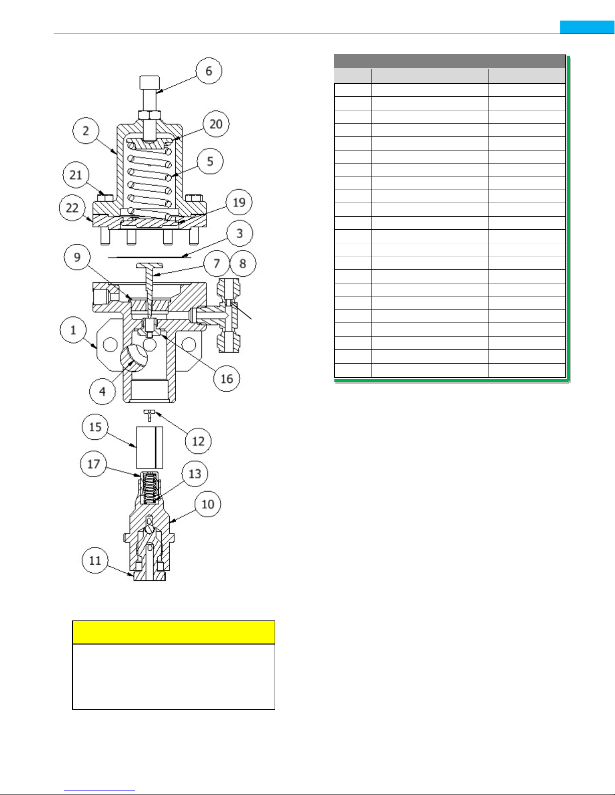
chamber at A.See Figure 8.
3. Inspect the orifice for debris or damage.
Clean or replace as required.
4. Slightly loosen the main valve diaphragm
nuts.
5. Then continue to loosen the nuts opposite the
side of working and pry the cover from the
valve body, if necessary. Allow the
condensate to drain away from where you are
working.
Note: The diaphragm cover may be heavy –
Care should be taken to properly support
it to avoid damage and/or personnel
injury.
6. Gently pry the diaphragm loose from the valve
body and allow any condensate to drain away
from your working position.
7. Once drained, continue to remove all
diaphragm nuts and cover.
8. Inspect the metal diaphragm for small cracks
or wrinkles. Replace as required.
9. Loosen the lock screw for the diaphragm plate
and then remove plate itself. Caution: The
main valve spring is exerting significant force
on the diaphragm plate. Proceed slowly.
10. Remove the top cover nuts and cover plate.
11. Remove the stem and disc assembly from the
valve and inspect the components for wear.
Minor wear can be corrected by lapping disc
and seat together with 400 grit lapping
compound.
12. Inspect the disc and seat for signs or debris
which could have caused leakage.
13. Check for erosion around the valve body of
the seat ring and the seat ring itself. Replace
or clean as required. If replaced, seat and
disc should be lapped.
14. Reassemble the valve stem assembly and
secure the top cover. Tighten the nuts
evenly.
15. Clean the diaphragm, diaphragm plate, and
gasket surfaces then reassemble making sure
the travel stop is installed properly.
16. Verify that the diaphragm plate setting is
correct. See dimension F, Figure 7, and
confirm that it is set to the value shown in the
table.
17. Verify that the diaphragm plate is securely
fastened to the stem with the locking screw.
Use High Temp Thread Locking Sealant as
required.
18. Confirm valve stem is operating properly by
pushing up on the diaphragm plate.
Note: Use caution as condensate may be
trapped in the upper portion of the valve
body if valve was not disassembled
completely.
19. Center the diaphragm on the cover. The bolts
will assist with centering.
20. Tighten the bolts evenly on the diaphragm
cover.
21. Reinstall the tubing line to the diaphragm
chamber.
22. After system is started again, recheck all
fasteners for tightness.
CAUTION