vissonic VIS-CRS02-B Manual de usuario

VIS-CRS02/03/04-B Conference
Auto Tracking Recorder
User Manual
V1.0
VISSONIC ELECTRONICS LIMITED

www.vissonic.com
2
The meaning of symbols
■ Safety instructions
For your safe and correct use of equipments, we use a lot of symbols on the equipments and in the
manuals, demonstrating the risk of body hurt or possible damage to property for the user or others.
Indications and their meanings are as follow. Please make sure to correctly understand these
instructions before reading the manual.
This is A level product, which may cause radio interference in the living
environment. In this case, users may need to take the feasible measures to
get around the interference.
Remind users that the dangerous voltage without insulation occurring
within the equipment may cause people suffer from shock.
CE certification means that the product has reached the directive safety
requirements defined by the European Union. Users can be assured about
the use of it.
SGS certification means that the product has reached the quality
inspection standards proposed by the world's largest SGS.
This product passed the ISO9001 international quality certification
(certification body: TUV Rheinland, Germany).
Warning: in order to avoid electrical shock, do not open the machine
cover, nor is the useless part allowed to be placed in the box. Please
contact the qualified service personnel.
■ General information instructions
It lists the factors leading to the unsuccessful operation or set and the
relevant information to pay attention.

www.vissonic.com
3
Important note
Warning
In order to ensure the reliable performance of the equipment and the safety of the user, please
observe the following matters during the process of installation, use and maintenance:
The matters needing attention of installation:
Please do not use this product in the following places: the place of dust, soot and electric
conductivity dust, corrosive gas, combustible gas; the place exposed to high temperature,
condensation, wind and rain; the occasion of vibration and impact . Electric shock, fire, wrong
operation can lead to damage and deterioration to the product, either;
In processing the screw holes and wiring, make sure that metal scraps and wire head will not
fall into the shaft of controller, as it could cause a fire, fault, or incorrect operation;
When the installation work is over, it should be assured there is nothing on the ventilated face,
including packaging items like dust paper. Otherwise this may cause a fire, fault, incorrect
operation for the cooling is not free;
Should avoid wiring and inserting cable plug in charged state, otherwise it is easy to cause
the shock, or electrical damage;
The installation and wiring should be strong and reliable, contact undesirable may lead to
false action;
For a serious interference in applications, should choose shield cable as the high frequency
signal input or output cable, so as to improve the anti-jamming ability of the system.
Attention in the wiring:
Only after cutting down all external power source, can install, wiring operation begin, or it
may cause electric shock or equipment damage;
This product grounds by the grounding wires .To avoid electric shocks, grounding wires and
the earth must be linked together. Before the connection of input or output terminal, please make
sure this product is correctly grounded;
Immediately remove all other things after the wiring installation. Please cover the terminals
of the products cover before electrification so as to avoid cause electric shock.
Matters needing attention during operation and maintenance:
Please do not touch terminals in a current state, or it may cause a shock, incorrect operation;
Please do cleaning and terminal tighten work after turning off the power supply. These
operations can lead to electric shock in a current state;
Please do the connection or dismantle work of the communication signal cable , the
expansion module cable or control unit cable after turning off the power supply, or it may cause
damage to the equipment, incorrect operation;
Please do not dismantle the equipment, avoid damaging the internal electrical component;
Should be sure to read the manual, fully confirm the safety, only after that can do program
changes, commissioning, start and stop operation.

www.vissonic.com
4
Matters needing attention in discarding product:
Electrolytic explosion: the burning of electrolytic capacitor on circuit boards may lead to
explosion;
Please collect and process according to the classification, do not put into life garbage;
Please process it as industrial waste, or according to the local environmental protection
regulations.

www.vissonic.com
5
Preface
This manual mainly describes the use, performance parameters and troubleshooting of
VIS-CRS02/03/04-B Conference Auto Tracking Recorder.
If the technical parameters and system usage in this manual are changed, the manufacturer will
update the version of the manual. Please use the latest user manual.
The copyright of the manual belongs to VISSONIC ELECTRONICS LIMITED. This manual is
protected by the Copyright Law of the People's Republic of China and other intellectual property
laws and regulations. Without permission, it is not allowed to copy part or all of the manual or
modify this manual.
Version
Update
Date
1.0
2023.10.21

www.vissonic.com
6
Contexts
1. Product description ......................................................................................................................... 8
2. Commissioning of the recorder .................................................................................................... 11
3. Functions of the controller and operating instructions .................................................................12
3.1. Main Interface. ...................................................................................................................12
3.1.1. User interface ..........................................................................................................12
4. Specification Parameter ................................................................................................................ 14
4.1.1. Main interface .........................................................................................................15
4.2. Monitoring interface .......................................................................................................... 15
4.3. Video Input Channel .......................................................................................................... 16
4.3.1. Channel interface ....................................................................................................17
4.3.2. Channel Settings .....................................................................................................17
4.4. PTZ control ........................................................................................................................22
4.5. Guide function ................................................................................................................... 23
4.5.1. Screen Split/Switching Effects ............................................................................... 23
4.5.2. Sound control/subtitles ........................................................................................... 24
4.5.3. Station label/OSD information/time .......................................................................25
4.5.4. Mainframe working status ......................................................................................27
4.5.5. Beginning and ending of video .............................................................................. 27
4.5.6. Video settings ..........................................................................................................28
4.5.7. One-touch start ....................................................................................................... 28
4.6. System function ................................................................................................................. 29
4.6.1. System Menu .......................................................................................................... 29
4.6.2. Channel ................................................................................................................... 30
4.6.3. File manager ........................................................................................................... 33
4.6.4. Safeguard ................................................................................................................ 34
4.7. Set up ................................................................................................................................. 36
4.7.1. Video Settings .........................................................................................................36
4.7.2. Guide settings ......................................................................................................... 40

www.vissonic.com
7
4.7.3. Live streaming settings ...........................................................................................44
4.7.4. Management Platform ............................................................................................ 46
4.7.5. Users and login ....................................................................................................... 46
4.7.6. Date and time ..........................................................................................................47
4.7.7. Disk and Storage .....................................................................................................48
4.7.8. Networks and Services ........................................................................................... 48
4.7.9. Engineering Settings ...............................................................................................51
4.7.10. Installation and commissioning ............................................................................55

www.vissonic.com
8
1. Product description
CRS-02/03/04-B is a conference recording and broadcasting equipment, integrated conference
recording, live, on-demand, intelligent guide, storage and other multi-functions in one, based on
embedded hardware architecture design, the product is highly stable. The device adopts
H.264/H.265 coding, with 4 HDMI video input interfaces, supporting 1080P@60fps image input. A
total of 2-way video output interface, multi-channel screen output to meet the playback system to
display images and can be used as an image input source for other systems (such as video
conferencing systems). The system supports simultaneous recording and live broadcasting in both
movie mode and resource mode, and the screen supports picture-in-picture and 1/2/3/4 split-screen
display and recording. Users can not only connect the mouse, monitor and guide desk locally for
guide recording and broadcasting operations, but also log in to the IE on the PC for remote guide
broadcasting.
Product Features:
Hardware and software pure embedded integrated architecture, stable and reliable.
Video can support 1920*1080 resolution from capture, recording to output.
H.264 advanced video compression technology.
Support up to 4-channel 1080P video synchronous capture and recording, 2-channel 1080P
video synchronous output.
.
www.vissonic.com
9
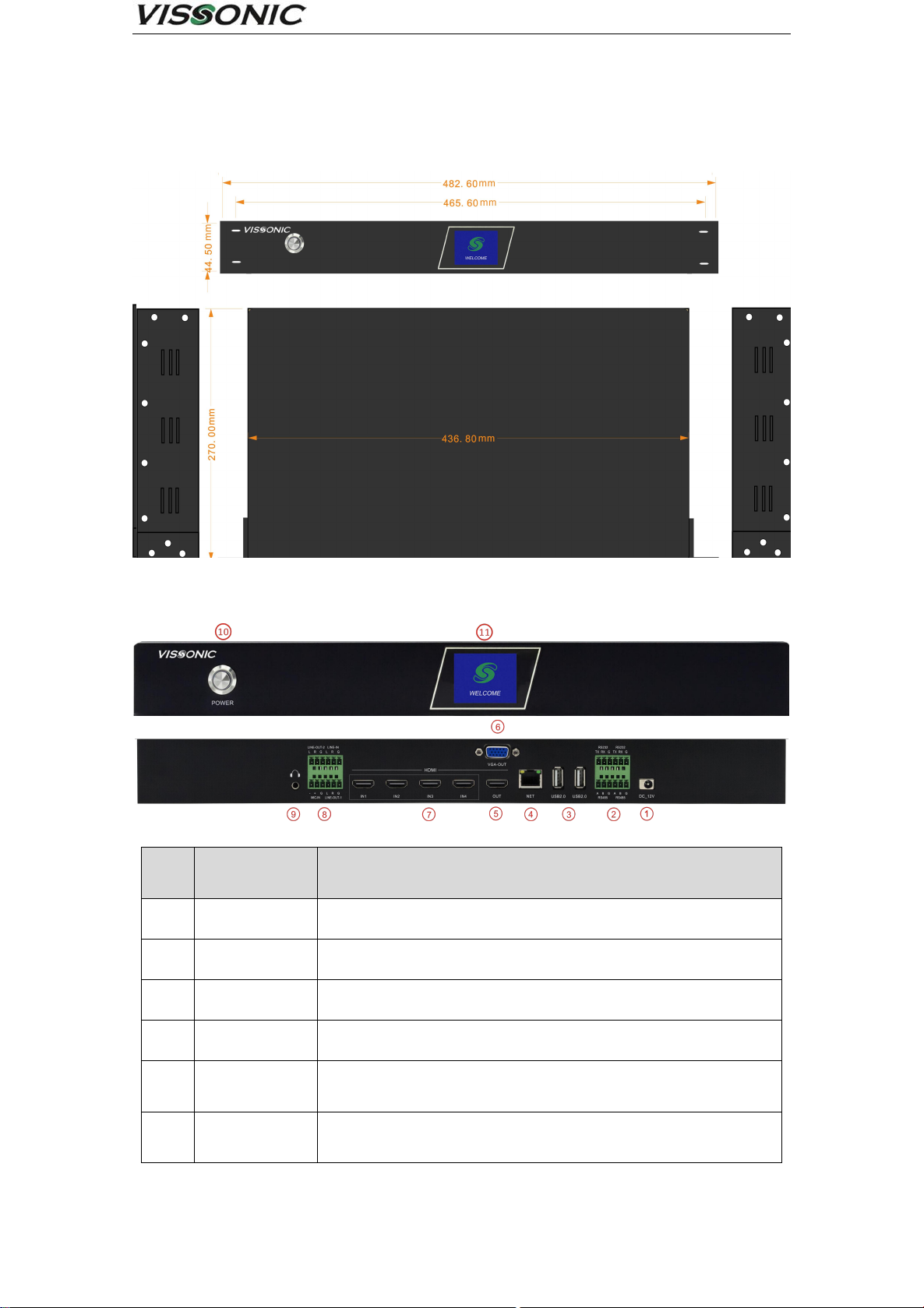
Main unit size and mounting holes:
Exterior dimension drawing
Front and rear panel interface definitions:
Front and rear panel interface diagram
grade
interface
identification
clarification
1
DC-12V
Power connector
2
RS232/RS485
Control serial port, external central control unit or console
3
USB2.0
Connect USB mouse, USB flash drive, removable hard drive, etc.
4
NET
1000M network port for device networking
5
HDMI OUT
1080P60 signal output, the output screen for the guide interface or
PGM (software can be set)
6
VGA OUT
1080P60 signal output, the output screen for the guide interface or
PGM (software can be set)

www.vissonic.com
10
7
HDMI IN 1-4
1080P60 signal input, support 4-way video signal input at the same
time
8
Line in
Mic in
Line out 1
Line out 2
Line in:Unbalanced Audio Input Connector
Mic in:Balanced Audio Input Connector
Line out 1:Unbalanced Audio Output Connector
Line out 2:Unbalanced Audio Output Connector
9
Monitor
3.5mm headphone monitor jack to monitor PGM channel sound
10
Power
Equipment power switch
11
LCD screen
For recording status, channel status, network information, storage
space, and logo display
Este manual sirve para los siguientes modelos
2
Tabla de contenidos
Manuales populares de Instrumento de medición de otras marcas


Endress+Hauser
Endress+Hauser Proline Promag 50 Especificaciones técnicas

Siemens
Siemens SITRANS F Coriolis FCT030 Manual de lista de piezas

KLINGER
KLINGER CMF V Series Manual de usuario

EXFO
EXFO FTB-2 Manual de operación y mantenimiento

Keysight
Keysight M8290A Manual de usuario

ADTEK
ADTEK MW-5 Manual de usuario