Viewpro DDL24E-ESPB Manual de usuario

Video and Data Transmitter
DDL24E-ESPB

Content
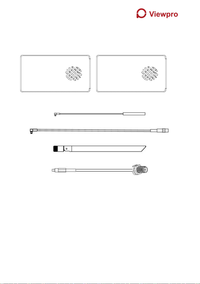
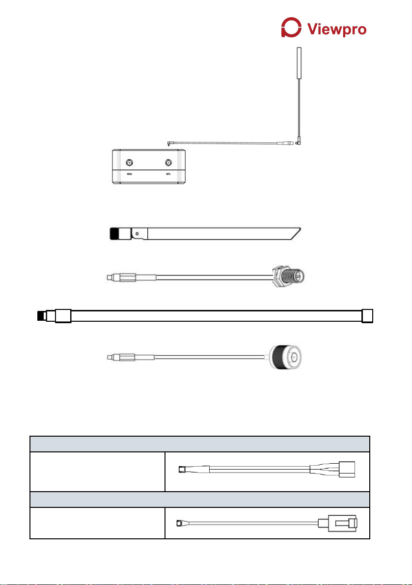
1. Package Contents...................................................................................... 1
2. Product Description.................................................................................... 4
2.1. Parameters...................................................................................... 4
2.2. Air Unit Interfaces........................................................................... 4
2.3. Ground Unit Interfaces...................................................................6
3. Installation....................................................................................................8
3.1. Air Unit Installation..........................................................................8
3.1.1. Antenna installation............................................................8
3.1.2. Power supply.....................................................................10
3.1.3. Connection to camera......................................................11
3.1.4. Connection to flight controller (RC & telemetry).......... 12
3.2. Ground Unit Installation...............................................................13
3.2.1. Antenna installation..........................................................13
3.2.2. Power supply.....................................................................13
3.2.3. Telemetry connection...................................................... 14
3.2.4. Connection to remote controller.....................................15
3.2.5. Setup video output........................................................... 15
3.2.6. Use Viewpro System........................................................ 16
4. Software..................................................................................................... 18
4.1. Installation......................................................................................18
4.2. Software Language...................................................................... 20
4.3. Device Info.....................................................................................22
4.4. Status............................................................................................. 22
4.5. Configuration................................................................................. 23
4.5.1. Encryption Configuration.................................................23
4.5.2. Mode configuration...........................................................24
4.5.3. Telemetry configuration...................................................25
4.5.4. Remote control mode configuration.............................. 26
4.6. Frequency Scan............................................................................26
4.7. Upgrade......................................................................................... 27
4.8. View Live Video............................................................................ 28
5. Applications............................................................................................... 29
5.1. Applications of system in detail.................................................. 29
5.2. Applications of RC........................................................................29
5.2.1. FRSKY remote controller................................................ 30
5.2.2. FUTABA remote controller..............................................31
5.3. Telemetry connection...................................................................31
6. Notes.......................................................................................................... 31
6.1. Link performance..........................................................................31

6.2. How to select Frequency.............................................................33
6.3. Firmware update...........................................................................36
6.4. Bind operation............................................................................... 37
6.5. Telemetry & RC............................................................................ 37
7. FAQ.............................................................................................................38

1
1. Package Contents
Air Unit & Ground Unit
Air unit antenna & feeder line ×2
(2.4G antenna for air unit)
(2.4G feeder extension line for air unit)
(1.4G antenna for air unit)
(1.4G feeder extension line for air unit)
Use feeder extension line of air unit

2
Ground unit antenna & feeder line ×2
(2.4G antenna for ground unit)
(2.4G feeder line for ground unit)
(1.4G antenna for ground unit)
(1.4G feeder line for ground unit)
Air Unit Cables
Power cable x1
This is used to connect the
output of a battery to the power
input of the air unit.
RJ45 cable x1
This is used to connect the
ETH output of camera to the
ETH input of the air unit.

3
RC cable x1
This is used to connect the
PPM/S.bus port of flight
controller to the RC port of the
air unit.
Serial cable x1
This is used to connect the
telemetry port of flight controller
to the serial port of the air unit.
USB cable(Micro to Type-A)×1
This is used to connect the
USB port of a PC or a cell
phone, to the Micro USB port of
the ground unit.
Ground Unit Cables
Power cable x1
This is used to connect the
output of a battery to the
power input of the air unit.
RJ45 cable x1
This is used to connect the
ETH output of ground unit to
the ETH input of a PC or
laptop.
RC cable x1
This is used to connect the
training port of a remote
controller to the RC port of the
ground unit.
Serial cable (UART) x1
This is used to connect the
telemetry port of ground
station to the serial port of the
ground unit.
USB cable (Micro to Type-A)×1 (share with air unit one)
This is used to connect the
USB port of a PC or a cell
phone, to the Micro USB port
of the ground unit.

4
2. Product Description
2.1. Parameters
Frequency
1.400GHz-1.495GHz, 2.4GHz-2.483GHz,
(Customizable)
Band width
2.5MHz (uplink), 10MHz(downlink)
Power
27dBm (FCC), 20dBm (CE)
Modulation
OFDM
Constellation
BPSK, QPSK, 16QAM
FEC
LDPC (1/2, 2/3, 3/4, 5/6)
Duplex
TDD
Downlink throughput
2.3Mbps ~ 12Mbps
Uplink throughput
115.2kbps
Encryption
AES 128, AES 256
Interface
Ethernet, Serial, PPM/S.BUS
Consumption
6.8W(ground unit) / 7.8W(air unit)
Dimension
77.8X47.3X23.5mm
Weight
97g
Rated voltage/current
DC12V/1.2A (or 3S lithium battery)
Working temperature
-30°C ~55°C
2.2. Air Unit Interfaces
1Power Input Port
Connect a 12V power source to this port. The power source can be from a battery,
or can be from a power adaptor when the ground unit is upgraded on the ground.
The power supply recommended 3s battery.
2RJ45 Port
②
③
④
⑤
①

5
Connect the ethernet output of camera to the ethernet input of the air unit.
3Serial Port (UART)
Connect this port to the telemetry port of a flight controller for telemetry
communication with the ground unit. UART signal: LVCMOS-3.3V.
4Remote Control Port (RC)
Connect this port to the PPM/S.Bus port of a flight controller for remote control
communication with the ground unit. Pin V + can provide 5V power supply.
5Micro USB Port
Connect this port to the USB port of a PC or Laptop, and use the Viewpro PC
program to upgrade firmware on the air unit.
1Bind Button
Press this button to perform the binding operation.
2LED 1
When this LED is on, it means the air-to-ground link is connected; when this LED
is off, it means the air-to-ground link is disconnected. (Not available for air unit)
3LED 2
When this LED is on, it means the ground -to-air link is connected; when this LED
is off, it means the ground -to-air link is disconnected. (Not available for air unit)
1RF2 Port
Connect the 2nd air unit antenna to this port.
2RF1 Port
Connect the 1st air unit antenna to this port.
1
1
3
2
②

6
1LED3
When this LED is flickering, it means the data link of the Ethernet network is
connected; when this LED is off, it means the data link of the Ethernet network is
disconnected.
2LED4
When this LED is on, it means the physical link of the ethernet port is connected;
when this LED is off, it means the physical link of the ethernet port is
disconnected.
1Fan Ventilation Outlet
Don’t block this fan ventilation outlet to ensure effective cooling.
2.3. Ground Unit Interfaces
1Power Input Port
Connect 12V power source to this port. The power source can be from a battery,
or can be from a power adaptor when the ground unit is upgraded on the ground.
The power supply recommended 3s battery.
2RJ45 Port
1
1
②
③
④
⑤
②

7
Connect this ethernet output port to the ethernet input port of a camera using the
supplied RJ45 cable.
3Serial Port (UART)
Connect this port to the telemetry port of a remote controller, or the serial port of
a ground control station to setup a telemetry link between the drone and the
remote controller or the ground control station. UART singal: LVCMOS-3.3V.
4Remote Control Port (RC)
Connect this port to the training PPM/S.bus port of a remote controller. Remote
controller can use ViUlinxTM uplink to communicate with the drone. Pin V + can
provide 5V power supply.
5Micro USB Port
Connect this port to the USB port of a PC or Laptop, and use the Viewpro PC
program to upgrade firmware on the air unit.
1Bind Button
Press this button to perform the binding operation.
2LED 1
When this LED is on, it means the air-to-ground link is connected; when this LED
is off, it means the air-to-ground link is disconnected.
3LED 2
When this LED is on, it means the ground -to-air link is connected; when this LED
is off, it means the ground -to-air link is disconnected.
1RF2 Port
1
②
Tabla de contenidos
Otros manuales de Transmisor de Viewpro
Manuales populares de Transmisor de otras marcas

Dejero
Dejero EnGo 3x Manual de usuario

Rosemount
Rosemount 4600 Manual de usuario

Speaka Professional
Speaka Professional 2342740 Manual de usuario

trubomat
trubomat GAB 1000 Manual de usuario

Teledyne Analytical Instruments
Teledyne Analytical Instruments LXT-380 Manual de usuario

Rondish
Rondish UT-11 Manual de usuario


