Venstar T1100REC Manual de usuario

Venstar Inc. 08/07
Use with most Air Conditioning & Heating Systems including: 1 or 2 Stage
Electric Cooling & 2 Stage Gas Heating, Heat Pump, Electric or Hydronic Heat.
residential
T1100REC
WIRELESS
THERMOSTAT
RECEIVER
INSTALLATION
INSTRUCTIONS
INSTALLATION
INSTRUCTIONS
Wireless
Digital
Thermostat
Receiver
Wireless
Digital
Thermostat
Receiver
HEAT
COOL HEAT
PUMP
Wireless Operation
Receives up to 4 Thermostats
Flexible Installation Locations
May be Mounted at Old
Thermostat Location or
with the Furnace
up to
& 2-cool
up to
& 2-cool
2-heat
2-heat
USE IN
CONJUNCTION
WITH T1100RF
USE IN
CONJUNCTION
WITH T1100RF
Control up to 2 Heat &
2 Cool Stages

This receiver is designed to operate from 0-70 C
This device complies with Part 15 of the FCC
Rules. Operation is subject to the following
two conditions: (1) this device may not
cause harmful interference, and (2) this
device must accept any interference
received, including interference that may
cause undesired operation.
C
c
FT1100REC
FCC ID MUH-T10016
CAUTION Follow Installation Instructions carefully.
DISCONNECT POWER TO THE HEATER -
AIR CONDITIONER BEFORE REMOVING
THE OLD THERMOSTAT AND INSTALLING
THE NEW THERMOSTAT.
WARNING
Step #1: Preparation
Step #2: Remove & Replace
Old Thermostat
Step #3: Dip Switch Settings
Step #4: Wire Connections
Troubleshooting
2
3
4
6
15
Table Of Contents
Step #5: Test Operation
16
Page 1
P/N T1100REC
Venstar Inc. 08/07

STEP #1
PREPARATION
Drill with 3/16
inch Drill Bit
(when not using
j-box)
Proper installation of the thermostat will be
accomplished by following these step by step
instructions. If you are unsure about any of
these steps, call a qualified technician for
assistance.
Assemble tools.
Flat Blade
Screwdriver
Wire cutter
& Stripper
Make sure your Heater/Air Conditioner is
working properly before beginning installation
of the thermostat.
Carefully unpack the thermostat. Save the
screws, wall anchors, and instructions.
Turn off the power to the Heating/Air
Conditioning system at the main fuse panel.
Most residential systems have a separate
breaker for disconnecting power to the furnace.
Page 2
HEAT
COOL
FAN
POWER
HEAT
COOL
FAN
POWER
HEAT
COOL
FAN
POWER
HEAT
COOL
FAN
POWER
HEAT
COOL
FAN
POWER

Remove the cover of the old thermostat.
If it does not come off easily check for
screws.
Loosen the screws holding the thermostat
base or subbase to the wall, and lift away.
Disconnect the wires from the old
thermostat. Tape the ends of the wires
as you disconnect them, and mark them
with the letter of the terminal for easy
reconnection to the new thermostat.
Keep the old thermostat for reference
purposes, until your new thermostat is
functioning properly.
STEP #2
REMOVE & REPLACE OLD THERMOSTAT
Page 3
HEAT
COOL
FAN
POWER
HEAT
COOL
FAN
POWER
HEAT
COOL
FAN
POWER
HEAT
COOL
FAN
POWER

1
2
4
8
16
32
EH
HP
ON
Antenna
Dip
switches
Circuit Board
1
2
4
8
16
32
EH
HP
1
2
4
8
16
32
EH
HP
Add all of the ON switches
to arrive at the House Code
number. All thermostats
communicating with this
receiver must have the
same House Code number.
If all of the number switches
are set to OFF, then the
House Code is 0 (zero).
ON Indicator
ON
Example:
House Code 10
2+8=10
O/B O/B
O/B
Disregard the numbers located
on the actual dip switch and
refer only to the markings on
the Receiver circuit board.
ON
1 2 3 4 5 6 7 8 9
ON
1 2 3 4 5 6 7 8 9
1 2 3 4 5 6 7 8 9
STEP #3
DIP SWITCH SETTINGS
House Code Setting
Page 4
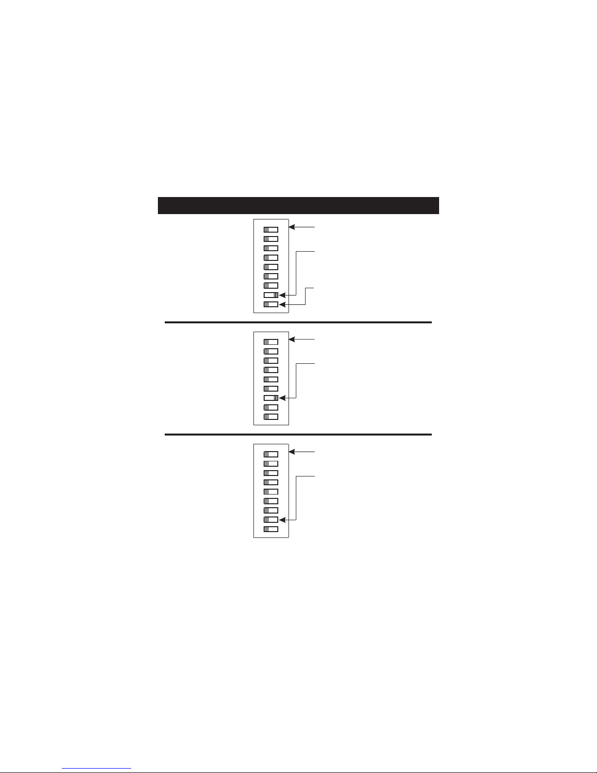
Heat Pump
O or B Reversing
Valve
Electric Heat
To configure the receiver
for Heat Pump operation,
slide the HP switch to the
ON position as shown.
The Reversing Valve polarity
can also be set. OFF = O
and ON = B.
ON Indicator
1
2
4
8
16
32
EH
HP
ON
O/B
1 2 3 4 5 6 7 8 9
To configure the receiver
for Electric Heat operation,
slide the EH switch to the
ON position as shown.
ON Indicator
1
2
4
8
16
32
EH
HP
ON
O/B
1 2 3 4 5 6 7 8 9
Gas Furnace
To configure the receiver
for Gas Heat operation,
slide all of the equipment
switches to the OFF position
as shown.
ON Indicator
1
2
4
8
16
32
EH
HP
ON
O/B
1 2 3 4 5 6 7 8 9
Equipment Settings
Page 5

If the terminal designations on your old
thermostat do not match those on the
new thermostat, refer to the chart below,
or the wiring diagrams that follow.
* C may not be used on all systems.
** O/B is used if your system is a Heat Pump.
Wire from the
old thermostat
terminal marked Function
In st al l on t he
new thermos tat
connector marked
G or F Fan G
Y1, Y or C Cooling Y1
W1, W or H Heating W1, O, B
W1, O, B**
PowerRh, R, M, Vr, A R
C
O/B
C *
Common
Rev. Valve
STEP #4
WIRE CONNECTIONS
Y2
W2
2nd Stage Cool
2nd Stage Heat
Y2
W2
Page 6
HEAT
COOL
FAN
POWER

Sample Wiring Diagrams
W2
Y2
R
O
W1
B
Y1
GC
*If using first stage electric heat, the “EH” dip switch must be
set to ON (see page 5).
Gas or Electric Heat
5 Wire, 1 Stage Cooling, 1 Stage Gas Heat Residential Gas or Electric Heat*,
Electric Cool, split systems & package
units.
POWER
R
COMPRESSOR
Y
W
GAS VALVE
or
STRIP HEAT
COMMON
C
FAN
G
Page 7

Sample Wiring Diagrams
Gas or Electric Heat
4 Wire, 1 Stage Cooling, 1 Stage Gas Heat Residential Gas or Electric Heat*,
Electric Cool, split systems & package
units.
W2
Y2
R
O
W1
B
Y1
GC
POWER
R
COMPRESSOR
Y
W
GAS VALVE
or
STRIP HEAT
FAN
G
*If using first stage electric heat, the “EH” dip switch must be
set to ON (see page 5).
Page 8
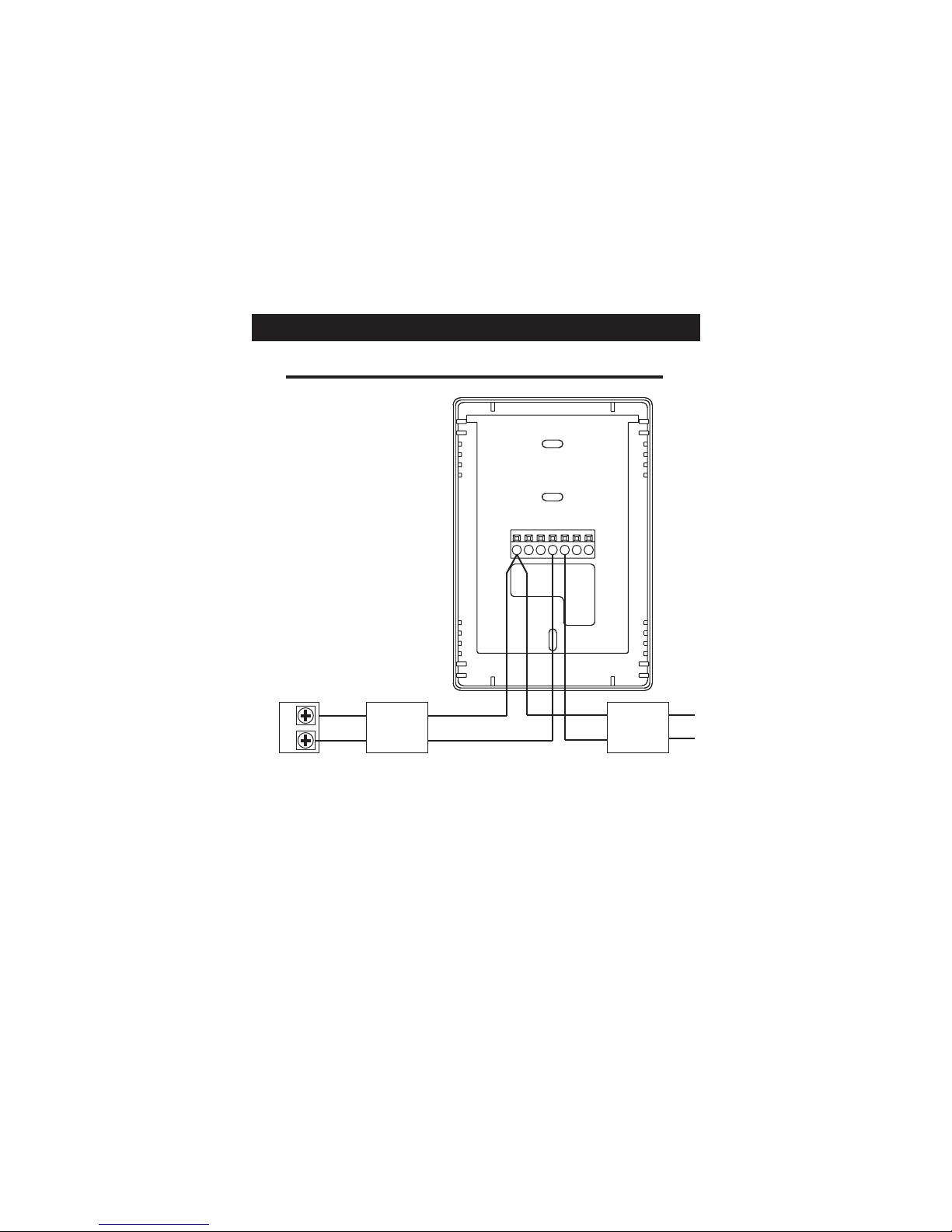
Sample Wiring Diagrams
Gas or Electric Heat
2 Wire, 1 Stage Gas or Electric Heat
*If using first stage electric heat, the “EH” dip switch must be
set to ON (see page 5).
Page 9
W2
Y2
R
O
W1
B
Y1
GC
RW
Furnace Board
24V Relay
White
Red
Brown
Orange
24VAC
200mA
Adaptor
Black
Black
The ACC0436 Wireless Thermostat Two-Wire Kit can be
purchased separately.
Tabla de contenidos


