Vaillant VRT 350f Manual de usuario

For the operator
Operating instructions
VRT 350f
VRT 350f
GB, IE
Operating instructions

Legal information
Document type: Operating instructions
Product: VRT 350f
Target group: Operator
Language: EN
Document number_version: 0020131979_00
Created on: 21.06.2012
Publisher/manufacturer
Vaillant GmbH
Berghauser Str. 40 D-42859 Remscheid
Telefon +49 21 91 18‑0 Telefax +49 21 91 18‑28 10
[email protected] www.vaillant.de
© Vaillant GmbH 2012
These instructions, or extracts thereof, may only be printed with the written consent of Vaillant GmbH.
All designations of products in these instructions are brand names/trade marks of the companies in ques-
tion.
We reserve the right to make technical changes.

Contents
0020131979_00 VRT 350f Operating instructions 3
Contents
1 Notes on the documentation............................... 4
1.1 Symbols and signs used ............................................... 4
1.2 Observing other applicable documents ................... 4
1.3 Document storage......................................................... 4
1.4 Applicability of the instructions................................. 4
2 Safety..................................................................... 5
2.1 Action-related warnings............................................... 5
2.2 Required personnel qualifications............................. 5
2.3 General safety information ......................................... 6
2.4 CE label............................................................................. 6
2.5 Intended use ................................................................... 7
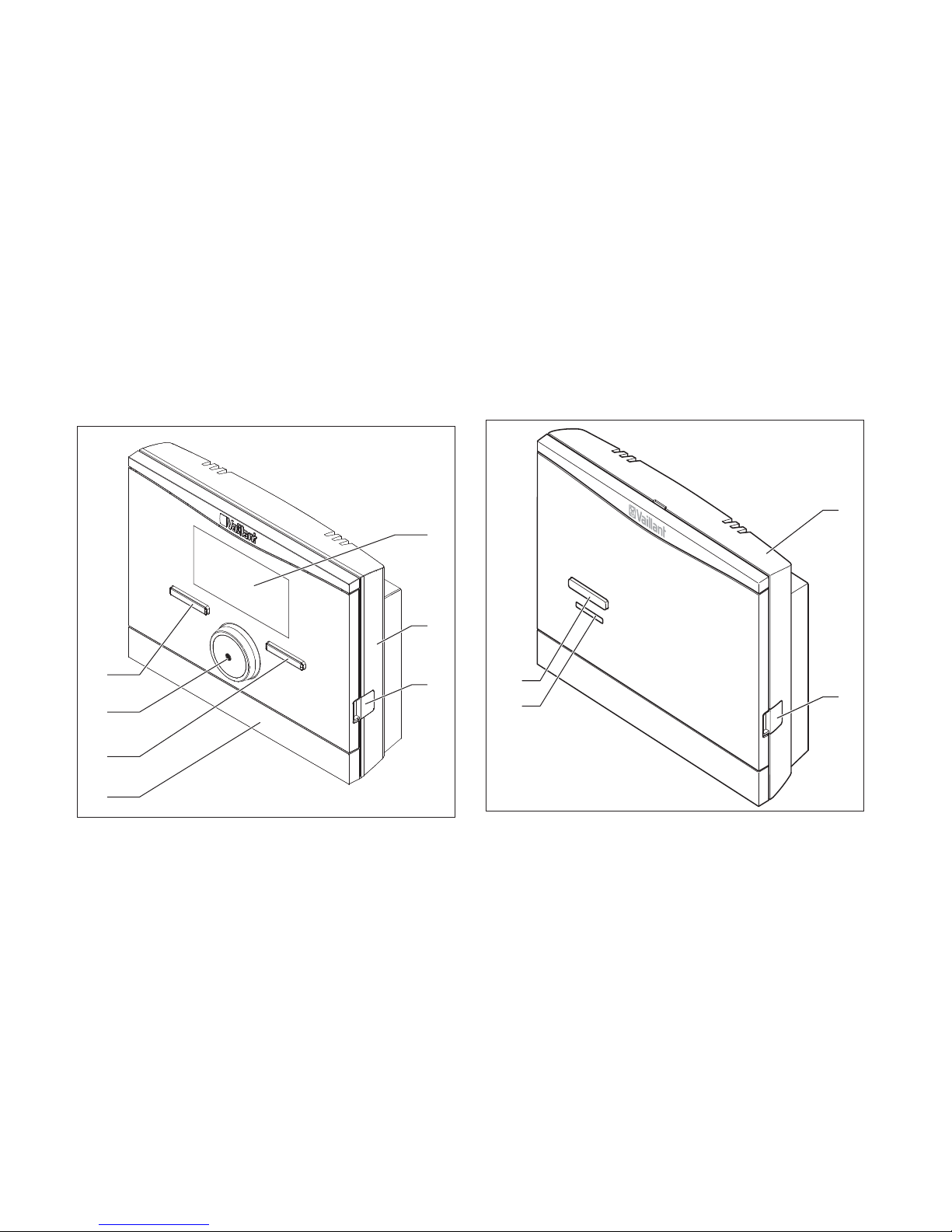
3 Overview of the equipment.................................. 8
3.1 Unit design....................................................................... 8
3.2 Identification plate ........................................................ 9
3.3 Serial number ................................................................. 9
3.4 Control function ............................................................. 9
3.5 Frost protection function........................................... 10
4 Operating ............................................................. 10
4.1 Operating structure .................................................... 10
4.2 Operating concept........................................................ 13
4.3 Overview of setting and read-out options............. 18
5 Operating and display functions ...................... 23
5.1 Information................................................................... 23
5.2 Settings ......................................................................... 24
5.3 Operating modes .......................................................... 31
5.4 Special operating modes .......................................... 32
5.5 Messages ...................................................................... 34
6 Service and troubleshooting............................. 35
6.1 Cleaning the controller.............................................. 35
6.2 Detecting and rectifying faults................................ 35
6.3 Changing batteries ..................................................... 36
7 Decommissioning ............................................... 37
7.1 Replacing the controller............................................ 37
7.2 Recycling and disposal .............................................. 37
8 Guarantee and customer service..................... 38
8.1 Warranty ....................................................................... 38
8.2 Customer service........................................................ 38
9 Technical data .................................................... 38
9.1 Control........................................................................... 38
9.2 Radio receiver unit ..................................................... 39

1 Notes on the documentation
4Operating instructions VRT 350f 0020131979_00
1 Notes on the documentation
1.1 Symbols and signs used
Symbols
The following symbols may appear:
Warning symbol (→Page 5)
Information symbol
Symbol for a required action.
Symbol for the result of an action.
1.2 Observing other applicable documents
▶You must observe all instructions for use that are en-
closed with other components of your system.
1.3 Document storage
▶Store the enclosed operating instructions and all other
applicable documents in such a way that they are avail-
able whenever required and for any subsequent operat-
ors of the system.
1.4 Applicability of the instructions
These instructions apply for the following only:
Article number
Great Britain 0020124482

Safety 2
0020131979_00 VRT 350f Operating instructions 5
2 Safety
2.1 Action-related warnings
Classification of action-related warnings
The action-related warnings are classified in accordance
with the severity of the possible danger using the following
warning signs and signal words:
Warning symbols and signal words
Danger!
Imminent danger to life or risk of severe per-
sonal injury
Danger!
Risk of death from electric shock
Warning.
Risk of minor personal injury
Caution.
Risk of material or environmental damage
2.2 Required personnel qualifications
These instructions are aimed at those who are able to oper-
ate a heating installation but do not have any special tech-
nical knowledge or experience.
2.2.1 Instructed operator (Operator)
Definition:
Instructed
operator
The operator is charged with operation and
maintenance of the unit. He/she must ensure
compliance with maintenance intervals. He/she
does not require any special technical know-
ledge or experience.
The operator must have been instructed in
the following topics by the authorised skilled
tradesman.
–General safety information
–Function and location of safety devices on
the system
–Operation of the unit
–Energy-saving operation
–Maintenance operations

2 Safety
6Operating instructions VRT 350f 0020131979_00
2.3 General safety information
2.3.1 Installation only by a skilled tradesman
Installation of the unit can be only carried out by an ap-
proved, skilled tradesman. This skilled tradesman is also
responsible for proper installation and start-up.
2.3.2 Risk of scalding from hot water
There is a risk of scalding at the hot water draw-off points
if the set target temperature is greater than 60 °C. Young
children and elderly persons are particularly at risk, even at
lower temperatures.
▶Select a moderate target temperature.
2.3.3 Danger caused by a malfunction
▶Ensure that air can circulate freely around the controller,
and that the controller is not covered by furniture, cur-
tains or other objects.
▶Ensure that all radiator valves in the room where the
controller is fitted are fully open.
▶Only operate the heating installation when it is in a tech-
nically perfect condition.
▶Ensure that any faults and damage that may negatively
affect safety are rectified immediately.
2.3.4 Frost damage caused by switching the
appliance off
If you switch off the heating installation, parts of the heat-
ing installation may be damaged by frost.
▶Do not disconnect the heat generator from the mains
power.
▶Leave the heating installation main switch in the "1" posi-
tion.
2.3.5 Frost damage caused by excessively low
room temperature
If the room temperature is set too low in individual rooms,
sections of the heating installation might be damaged by
frost.
▶If you are absent during a frosty spell, ensure that the
heating installation remains in operation and the rooms
are warmed adequately.
▶Please note the frost protection function.
2.4 CE label
The CE label documents that the controller com-
plies with the fundamental requirements of the relevant dir-
ectives.

Safety 2
0020131979_00 VRT 350f Operating instructions 7
2.5 Intended use
State-of-the-art
The controller is a state-of-the-art unit manufactured in
accordance with recognised safety regulations.
Even so, in the event of inappropriate or non-intended use,
damage to the appliance and other property may arise.
The controller controls a heating installation with Vaillant
heat generators with eBUS interface in a way that is room-
temperature-controlled and time-dependent.
The controller can control the hot water generation from a
connected DHW cylinder.
You should only remove the controller temporarily from the
wall-mounting base, e.g. to adjust the settings. Apart from
that, you should always operate it in conjunction with the
wall-mounting base.
Improper use
Any other use, or use beyond that specified, shall be
considered improper use. Any direct commercial or
industrial use is also deemed to be improper. The manufac-
turer/supplier is not liable for any resulting damage. The
user alone bears the risk.
Improper use of any kind is prohibited.
Other applicable documents
Intended use includes the following:
–observance of accompanying operating, installation and
servicing instructions for the Vaillant product as well as
for other parts and components of the system
–compliance with all inspection and maintenance condi-
tions listed in the instructions.

3 Overview of the equipment
8Operating instructions VRT 350f 0020131979_00
3 Overview of the equipment
3.1 Unit design
Radio controller
1
3
2
6
5
4
7
1 Display
2 Wall-mounting base
3 Diagnostics socket
4 Wall-mounting base cover
5 Right-hand selection
button
6 Rotary knob
7 Left-hand selection button
Radio receiver unit
2
4
3
1
1 Wall-mounting base
2 Diagnostics socket
3 LED
4 Teach-in button

Overview of the equipment 3
0020131979_00 VRT 350f Operating instructions 9
3.2 Identification plate
The identification plate is located on the rear panel of the
controller casing.
3.3 Serial number
The 10-digit article number can be found in the serial num-
ber. You can view the serial number under Menu →Inform-
ation Serial number. The article number is found in the
second line of the serial number.
3.4 Control function
The controller controls the Vaillant heating system and hot
water generation of a connected domestic hot water cylin-
der.
3.4.1 Heating installation
The controller is a room-temperature-controlled control-
ler and must be installed in the living room. You can use the
controller to set a desired temperature for different times
of the day and for different days of the week. The temper-
ature sensor measures the room temperature and forwards
the values to the controller. At lower room temperatures,
the controller switches the heat generator on. Once the
room temperature reaches the desired set temperature, the
controller switches the heat generator off. The controller
therefore reacts to the fluctuations of the room temperat-
ure and constantly controls the room temperature to the
temperature that you have set.
The controller is powered by batteries. Data transmission
between the controller and the radio receiver unit takes
place via radio communication. Data transmission between
the radio receiver unit and the boiler takes place via an
eBUS interface, which also provides the power supply for
the radio receiver unit.
Data communication and the power supply for the control-
ler is provided via eBUS interface. The controller can be
equipped with the Vaillant diagnostics software and the
Vaillant Internet communication system for remote dia-
gnostics and remote settings.
3.4.2 Hot water generation
You can use the controller to set the temperature and time
for the hot water generation. The heater heats the water in
the domestic hot water cylinder until it reaches the set tem-
perature. You can set a time period during which hot water
should be available in the domestic hot water cylinder.

4 Operating
10 Operating instructions VRT 350f 0020131979_00
3.5 Frost protection function
The frost protection function protects the heating system
and apartment from frost damage.
The frost protection function monitors the room temperat-
ure. If the room temperature
–falls below 5 °C, the controller switches the heater on
and controls the system to a target room temperature of
5 °C.
–exceeds 5 °C, the heater is switched off but the room
temperature monitoring remains active.
4 Operating
4.1 Operating structure
4.1.1 Access level for the operator
Through the access level for the operator, you access im-
portant information and set-up options which do not require
any special prior knowledge. Via a menu structure, you can
access configurable or read-only values.
4.1.2 Access level for the skilled tradesman
The skilled tradesman will set further values for the heating
installation via the access level for the skilled tradesman.
The settings may only be made by someone with specialist
knowledge; this level is therefore code-protected.
4.1.3 Menu structure design
The menu structure of the controller is split into three
levels. There are two selection levels and one setting level.
From the basic display, you can access selection level 1 and,
from there, you can access the menu structure for one level
up or down. The setting level is accessed from the lowest
selection level.
Otros manuales para VRT 350f
3
Tabla de contenidos
Otros manuales de Controladores de temperatura de Vaillant

Vaillant
Vaillant VRT 340f Manual de usuario

Vaillant
Vaillant VRC 400 Operating and Hoja de especificaciones

Vaillant
Vaillant VRT 230 Operating and Manual de usuario

Vaillant
Vaillant VRT 50 Manual de usuario

Vaillant
Vaillant VRC 430f Hoja de especificaciones

Vaillant
Vaillant VRC 470 Manual de usuario

Vaillant
Vaillant VRC 470 Guía de inicio rápido

Vaillant
Vaillant VRT 230 Operating and Manual de usuario

Vaillant
Vaillant VRC 470 Manual de usuario

Vaillant
Vaillant VR 92/3 Manual de usuario


