Vaillant VR 81 Manual del propietario

Supplement to the operating and installation manual VR 81 0020124743_00 1
The VR 81/2 remote control unit can be used together
with the VRC 430/VRC 430f and VRC 470 compensator
types.
>Please follow the installation, start-up and operating
instructions below.
VRC 430/VRC 430f
>Please follow the operating and installation manual
(no.0020044392) supplied with the remote control
unit.
VRC 470
>During installation and start-up, follow the operating
and installation manual (no. 0020044392) supplied
with the remote control unit.
>During operation, please note the following:
On the VR 81/2, you can only set the target room tem-
perature. All other settings, e.g. setting operating modes
or time windows, can only be made on the VRC 470 con-
troller.
1
2
Fig. 1.1 Overview of the equipment
1 Display
2 Setting dial (turn and click)
Fig. 1.2 Basic display
The current room temperature is shown in the "basic
display". In addition, various symbols in the display indi-
cate maintenance and error messages.
Supplement to operating and installation manual
no. 0020044392 for the VR 81 remote control unit

2Supplement to the operating and installation manual VR 81 0020124743_00
Operating concept
The VR 81/2 remote control unit is operated using a con-
trol that works according to the Vaillant "Turn and click"
operating concept.
Turn the control:changes adjustable values
Click the control: confirms the value
There are two operating levels:
– The operator level, in which you can read off and
change the target room temperature,
– The heating engineer level, which is reserved for the
heating engineer. Used for displaying and adjusting/
changing specific parameters for the heating installa-
tion.
A flashing area in the display indicates parameters that
can be changed.
Setting the room temperature
The current room temperature is displayed on the basic
display.
>Turn the control.
The current room temperature disappears. The set tar-
get room temperature appears and flashes. You can now
change the set target room temperature.
>Turn the control anti-clockwise or clockwise to
decrease or increase the target room temperature.
The basic display reappears after five seconds. The new
target room temperature is applied.
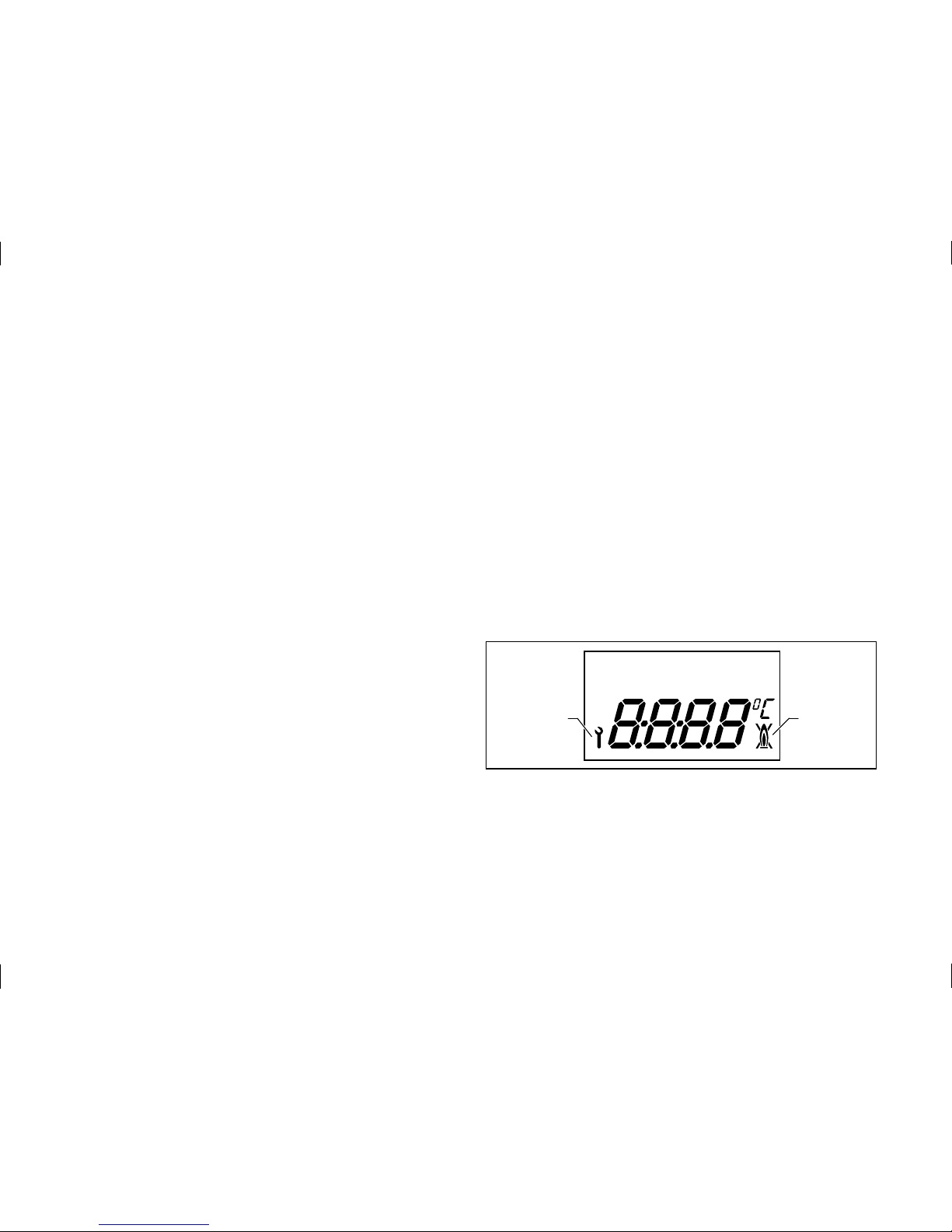
Status messages and error messages
2
1
Fig. 1.3 Display overview
1 Heating appliance maintenance request or heating engineer
level
2 Heating appliance fault

Supplement to the operating and installation manual VR 81 0020124743_00 3
The " " symbol appears in the display
Either you are at the heating engineer level or there is a
maintenance request from the heating appliance.
a) The operating level for the heating engineer is
shown in the display.
bCaution!
Malfunctions due to improper settings.
Only your heating engineer can change the
settings on the heating engineer level.
>Do not change any settings.
>Wait five minutes until the basic display
automatically appears.
b) If the symbol does not go out after five minutes,
there is a maintenance request from the heating
appliance.
>Contact your heating engineer.
The " " symbol is shown in the display
There is a fault in the heating appliance.
>Contact your heating engineer.
"Err" appears in the display:
Fig. 1.4 Error message
There is an error on the VR 81/2 remote control unit or a
communication error on the eBUS.
>Contact your heating engineer.

0020124743_00 GBIE 032011 – Subject to change
Manufacturer
Supplier

Operating and Installation Manual
VR 81
Remote control unit for VRC 430
GB
For the operator / for the heating engineer

Contents
Notes on the documentation........................................... 3
1.1 Storage of the documents ............................................ 3
1.2 Symbols used ................................................................... 3
1.3 Validity of the instructions ........................................... 3
1.4 Other applicable documents ........................................ 3
1.5 CE label..............................................................................4
Operating instructions
1 Appliance features................................................. 5
2 Safety ...................................................................... 5
3 Instructions for operation .................................... 6
3.1 Intended use.....................................................................6
3.2 Ambient conditions......................................................... 6
3.3 Care .................................................................................... 6
3.4 Factory customer service and manufacturer's
guarantee.......................................................................... 7
3.5 Recycling and disposal................................................... 7
4 Operation ................................................................ 8
4.1 Overview operating and display front........................8
4.2 Operating concept .........................................................10
4.3 Setting the target room temperature.......................10
4.4 Setting the operating mode .........................................11
4.5 Setting additional parameters .....................................11
4.6 Changing the target room temperature....................11
5 Status and error messages .................................13
Installation instructions
6 Information on installation and operation.........14
6.1 Intended use....................................................................14
7 Safety instructions and regulations ..................14
8 Assembly ...............................................................15
8.1 Assembly location..........................................................15
8.2 Installing the remote control unit..............................15
9 Electrical installation...........................................16
9.1 Connecting the remote control unit.......................... 17
10 Start-up..................................................................19
10.1 Activating/exiting the installer level..........................19
10.2 Setting the parameters.................................................19
10.3 Handover to the operator...........................................20
11 Technical data ......................................................20
Contents
Operating and Installation Manual VR 81 0020044392_002

Notes on the documentation
The following notes are intended to help you throughout
the entire documentation. Further documents apply in
conjunction with this operating and installation manual.
We accept no liability for any damage caused by failure to
observe these instructions.
1.1 Storage of the documents
Please store this operating and installation manual and all
related documents in such a way that they are available
whenever required.
1.2 Symbols used
Observe the safety information in these operating and
installation instructions when operating and installing the
appliance!
dDanger!
Immediate risk of serious injury or death!
eDanger!
Danger of death by electric shock!
HAttention!
Danger of burning and scalding!
aCaution!
Potentially dangerous situation for the product
and environment!
hNote
Useful information and tips.
Symbol for a necessary task
1.3 Validity of the instructions
These operating and installation instructions apply
exclusively for VR 81 appliances with the following article
numbers:
0020028539, 0020028541, 0020028542
For the operator:
The article number of your remote control unit can be
obtained from your expert technician.
1.4 Other applicable documents
Please observe all operating instructions for components
of the system. These operating instructions are enclosed
with the relevant components of the system and addition-
al devices.
Notes on the documentation
3Operating and Installation Manual VR 81 0020044392_00

Notes on the documentation
1.5 CE label
The CE label confirms that the VR 81 remote control unit
complies with the fundamental requirements of the
following directives.
– Electromagnetic compatibility directive
(Guideline 89/336/EEC)
– Low voltage directive (Guideline 2006/95/EEC)
Operating and Installation Manual VR 81 0020044392_004

Appliance features 1
Safety 2
Operating instructions
hNote
Have your expert technician explain the operati-
on of the VR 81 remote control unit once the in-
stallation is complete. This will prevent involun-
tary changes to the settings.
Note
Also read the operating manual for the VRC 430
controller. This describes how important
parameters of your heating system
can be adjusted (e.g. time window). An
explanation of technical terms and important
functions is provided in alphabetical order at the
end of this document.
1 Appliance features
The VR 81 remote control unit is a wired remote control
unit for a heating circuit and is used in combination with
the VRC 430 controller. Communication with the boiler is
achieved via a 2-lead bus line (eBUS).
You can adjust or modify the main functions via the VR 81
remote control unit (operating mode, target room
temperature).
Only one VR 81 remote control unit can be used.
Product specifications
– eBUS interface
– Symbol display
– Operation using a single dial based on the "Turn and
Click" principle
- The remote control unit can be mounted separately on
the wall
2 Safety
The VRT 81 remote control unit must be installed by a
recognised expert technician who is also responsible for
ensuring that existing standards and regulations are
observed.
We accept no liability for any damage caused by failure to
observe these instructions.
5Operating manual VR 81 0020044392_00 VR 81 0020044392_00

3 Instructions for operation
3.1 Intended use
The VR 81 remote control unit is a state-of-the-art device
which has been constructed in accordance with the
standard safety regulations.
Even so, inappropriate or non-intended use may adversely
affect the appliance and other material assets.
A mixed or unmixed heating circuit can be controlled
remotely by the VRC 430 controller in conjunction with a
Vaillant boiler and eBUS interface using the VR 81 remote
control unit.
Any other use or extended use is considered to be use
other than intended. The manufacturer or supplier is not
liable for any resulting damage. The owner alone bears
any risk.
Intended use also includes observance of the operating
and installation instructions and all other documents also
have validity.
3.2 Ambient conditions
The VR 81 remote control unit may only be installed in dry
rooms.
Observe the following where the "Switch-on room temp."
function for the remotely controlled heating circuit is ac-
tivated at the VRC 430 controller:
– the VR 81 remote control unit must not be covered by
furniture, curtains or other objects;
– all radiators in the room where the VR 81 remote
control unit is fitted must be fully on.
Your heating engineer will advise you whether the
"switch-on room temp." is activated.
3.3 Care
hNote
Do not use abrasive materials or cleaning agents
that could damage the operator control
elements, parts of the casing or display.
Clean the casing of the VR 81 remote control unit with
a damp cloth.
Operating manual VR 81 0020044392_006
Tabla de contenidos
Otros manuales de Mando a distancia de Vaillant

Vaillant
Vaillant VR 91f Manual de usuario

Vaillant
Vaillant VR 920 Manual de usuario

Vaillant
Vaillant VAZ RC Manual de usuario

Vaillant
Vaillant 0020285219 Manual de usuario

Vaillant
Vaillant VR 91 Manual de usuario

Vaillant
Vaillant 0020260940 Manual de usuario

Vaillant
Vaillant VED/8 Manual de usuario

Vaillant
Vaillant VR 91f Manual de usuario