V-Tec D250 Manual de usuario

USER MANUAL
• Please read this manual carefully to ensure safe and correct operation
• Keep this manual well for future reference
RF CARD
RF CARD
RF CARD
RF CARD
RF CARD
RF CARD
DT607A/ID-S4DT607/ID/FE-S1 DT607/ID/FE-S2
DT607F/ID/FE-S4DT607/ID/FE-S3 DT607/ID/FE-S4
Model D250
2-wire series
Fisheye door station with Proximity Reader

CONTENTS
PARTS AND FUNCTIONS..................................................................................... 3
Part Names............................................................................................................. 3
Mounting................................................................................................................. 4
BASIC FUNCTIONS .............................................................................................. 6
Unlock Operations.................................................................................................. 6
Fisheye Camera ..................................................................................................... 6
External Motion Detection ...................................................................................... 6
SETUP INSTRUCTIONS........................................................................................ 7
Functions Setting Up .............................................................................................. 7
Setting Door Station Address ................................................................................. 8
Setting Door Station Calling Mode ......................................................................... 8
Setting Camera Resolution.................................................................................... 10
Setting Unlock Mode ............................................................................................. 10
Setting Unlock Time............................................................................................... 11
Setting Nameplate Illumination Mode.................................................................... 11
Setting Night View LED Illumination Mode............................................................ 12
Setting Ring-back Tone ......................................................................................... 12
Setting Image Display Mode.................................................................................. 13
Registering ID Card............................................................................................... 14
WIRING ................................................................................................................. 17
Connecting Electric Lock....................................................................................... 17
Connecting Basic One-to-one ............................................................................... 18
Connecting Multi Door Stations............................................................................. 18
Connecting Multi Monitors..................................................................................... 19
APPENDIX ............................................................................................................ 21
Precautions............................................................................................................ 21
Specication .......................................................................................................... 21
Cables and Requirments....................................................................................... 22

-3-
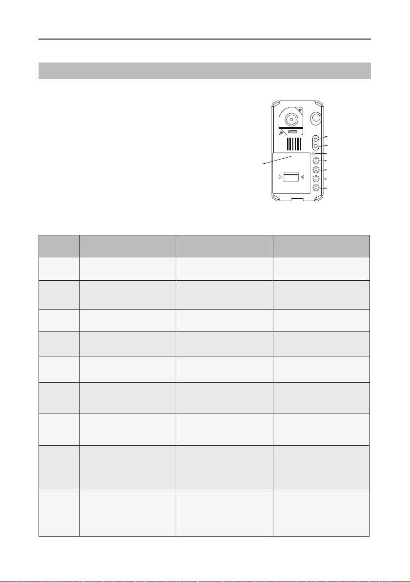
Parts
PARTS AND FUNCTIONS
[11]
[10]
[14]
[9]
[1]
[3]
[4]
[1]
[3]
[4]
[8]
[7]
[6]
[5]
[9]
[8]
[7]
[6]
[5]
[12]
[11]
[12]
[13]
[13]
[2]
[2]
Surface mounted
Flush mounted
[1] Microphone
[2] UNLOCK indicator
[3] Call indicator
[4] Call button
[5] Nameplate
[6] Front panel
[7] Speaker
[8] Night view LED
[9] Camera lens
[10] Rain cover
[11] Mounting hook
[12] Connection port
[13] Screw hole
[14] Mounting box

-4-
PARTS AND FUNCTIONS
Mounting
1 2 3 4 5
AcDbMLeader (ACDB_MLEADER_CLASS)
AcDbMLeader (ACDB_MLEADER_CLASS)
Rain cover
Rain cover
The distance between
the top of main unit
and rain cover should
be not less than 3mm.
Main unit
Main unit
≥3mm
1 2 3 4 5
AcDbMLeader (ACDB_MLEADER_CLASS)
AcDbMLeader (ACDB_MLEADER_CLASS)
AcDbMLeader (ACDB_MLEADER_CLASS)
1. Connect the cable
2. Drill holes in the wall to match the size of screw stoppers, then attach the rain cover and
main unit to the wall. The distance between the top of main unit and rain cover should be not
less than 3mm
3. Install the name plate
4. Attach the front panel to the main unit
5. Use the special screwdriver and the screws to x the panel
1. Drill a hole in the wall to match the size of mounting box, then install the mounting box
2. Loosen the high screws to install the name plate
3. Connect the cable
4. Attach the front panel to the mounting box,then use the special screwdriver and the screws to
x the panel
5. Finish the installation
Surface mounted
Flush mounted
The installation height is suggested to 145~160cm
* The camera angle view of surface mount model may be less than 1700

-5-
PARTS AND FUNCTIONS
Terminal description
Lock Control Jumper: To setthe type of lock
Motion Detector Connect Port: To connect external PIR motion detector
Main Connect Port: To connect the bus line and the electric lock
• L1,L2: Connect to the bus line, no polarity
• PL: External lock power input, connect to the power positive (power +)
• S+: Lock power(+) output
• S-: Lock power(-) output, connect to the power(-) input of lock (only when using the door
station to power the lock
1 2 3
Lock Control Jumper
PIR Motion Detector
Connect Port
+12V
GND
PIR
L1 L2
PL
S+ S-
Main Connect Port

-6-
BASIC FUNCTIONS
Unlock Operations
Unlocking with Proximity Fob/Card
When registered user fob/card has been shown to the proximity Reader, the UNLOCK indicator
lights up, the buzzer sounds, and the electric lock is unlocked
• Authorized user fob/card will make one beep sound,and the UNLOCK indicator will lightsup
• Unauthorized user fob/card will make 3 beep sounds
Fisheye Camera
External Motion Detection
Please note that this function requires the
monitor with sheye function to support.
The angle of view is 1700Image can be
zoomed as well
The door station is equipped with a terminal to
connect external PIR motion detector
If motion is detected, the door station will turn
security light on
Standard
door station angle
DT607
170 degree fisheye camera
12V
Motion
detector
GND
PIR
-7-
SETUP INSTRUCTIONS
Functions Setting Up
KEY_1
KEY_2
KEY_3
KEY_4
KEY_SET
LED_UNLOCK
LED_TALK
LED_NAME
RF CARD
This section explains the settings of each
function,please refer to the following table
To perform the settings for the function
you want,you should remove front cover.
Please refer to the sketch
Each setting will be indicated by lighting up
of the LED indicatorsand by the sounding
of the buzzer
Order SettingsSetting range Default value
1Door station address 0~3 0
2Door station calling
mode Standard/Group calling mode Standard calling mode
3Camera resolution High/Low High
4Unlock mode 0:opened/1:closed 0:opened
5Unlock time 01 to 99 seconds 1 seconds
6Nameplate
illumination mode On/Off/Auto On
7Night view LED
illumination mode On/Off/Auto Auto
8Ring tone
Ring once
Ring continuously
No ring tone
Ring once
9Image display mode
Alternate switching mode
Zoom mode
Full screen mode
Alternate switching mode

-8-
Door Station Address Setting
Setting Door Station Calling Mode
4 addresses can be assigned. The address can be modied either before or after
installation
Default address is 0. To change the address, please follow the steps:
UNLOCK Indicator:OFF
TALK Indicator:OFF Buzzer Beep+, Beep
UNLOCK Indicator:OFF
TALK Indicator:OFF
Buzzer Beep+
In standby press
KEY_SET button once
Press KEY_1 button to set
the first door station
Press KEY_2 button to set
the second door station
Press KEY_3 button to set
the third door station
Press KEY_4 button to set
the fourth door station
UNLOCK Indicator:OFF
TALK Indicator:OFF
Buzzer Beep,Beep
UNLOCK Indicator:OFF
TALK Indicator:OFF
Buzzer Beep,Beep,Beep
UNLOCK Indicator:OFF
TALK Indicator:OFF
Buzzer Beep,Beep,Beep,Beep
ID=0, for 1st door station ID=1, for 2nd door station ID=2, for 3rd door station ID=3, for4th door station
SETUP INSTRUCTIONS
• Press KEY_SET button to go into programming mode and change the address of door station by
pressing KEY1~4
• The LED_NAME indicator will blink until exit out programming mode
• No activity for 10 seconds will exit programming mode automatically
• Or press KEY_SET button four times to exit programming mode manually
There are two calling modes available: Standard calling mode and Group calling mode
Please know that the door station supplied in Standard calling mode by default

-9-
• If setting mode has not been exited, you can change the calling mode by pressing KEY1 circularly.
• The LED_NAME indicator will blink all the time until exit out the setting mode.
• If without any operation in 10 seconds, it will exit out setting mode automatically.
• In this step,press KEY_SET button three times to exit out the setting mode manually.
SETUP INSTRUCTIONS
Each call button will respond different addresses when set in different calling mode
Call button A: call the monitor with address 01
Call button B: call the monitor with address 02
Call button C: call the monitor with address 03
Call button D: call the monitor with address 04
Call button A: Call all monitors in group address
from 00~15 (one of the monitor should be set to 00)
Call button B,C,D: Call all monitors in group address
from 16~31 (one of the monitor should be set to 16)
UNLOCK Indicator:OFF
TALK Indicator:ON
Buzzer Beep+, Beep
In standby press
KEY_SET button twice
UNLOCK Indicator:OFF
TALK Indicator:ON
Buzzer Beep+
Press KEY_1 button to
activate Standard calling
mode for door station
UNLOCK Indicator:OFF
TALK Indicator:ON
Buzzer Beep, Beep
Press KEY_1 button again
to activate Group calling
mode for door station
Press KEY_1
A
B
C
A
B
C
D
RF CARDRF CARD
A A
B
RF CARDRF CARD
1.Standard calling mode (Address range 01-04 )
2.Group calling mode
To change this setting, please follow the steps:

-10-
Camera Resolution Setting
Unlock Mode Setting
High resolution of the camera is default.To change from High Resolution to Low Resolution,
please follow the steps:
2 unlock modes are available: Normally Opened and Normally Closed
Normally opened is default.To change the setting, please follow the steps:
UNLOCK Indicator:OFF
TALK Indicator:ON
Buzzer Beep+, Beep
In standby press
KEY_SET button twice
UNLOCK Indicator:OFF
TALK Indicator:ON
Buzzer Beep+
Press KEY_2 button to set the
camera to High resolution
UNLOCK Indicator:OFF
TALK Indicator:ON
Buzzer Beep, Beep
Press KEY_2 button again
to set the camera to Low
resolution
Press KEY_2
UNLOCK Indicator:ON
TALK Indicator:OFF
Buzzer Beep+, Beep
In standby press
KEY_SET button three
times
UNLOCK Indicator:ON
TALK Indicator:OFF
Buzzer Beep+
Press KEY_1 button to set
the unlock mode to
Normally opened
UNLOCK Indicator:ON
TALK Indicator:OFF
Buzzer Beep, Beep
Press KEY_1 button again
to set the unlock mode to
Normally closed
Press KEY_1
SETUP INSTRUCTIONS
• If setting mode has not been exited, you can change the camera resolution by pressing KEY2 circularly.
• The LED_NAME indicator will blink all the time until exit out the setting mode.
• If without any operation in 10 seconds, it will exit out setting mode automatically.
• In this step,press KEY_SET button three times to exit out the setting mode manually.
• If setting mode has not been exited, you can change the unlock mode by pressing KEY1 circularly.
• The LED_NAME indicator will blink all the time until exit out the setting mode.
• If without any operation in 10 seconds, it will exit out setting mode automatically.
• In this step,press KEY_SET button twice to exit out the setting mode manually.
Este manual sirve para los siguientes modelos
6
Tabla de contenidos
Otros manuales de Sistema de seguridad de V-Tec


Manuales populares de Sistema de seguridad de otras marcas


EDM
EDM Solution 6+6 Wireless-AE Manual de usuario

Highway Safety Group
Highway Safety Group EA401 Manual de usuario

Siren
Siren LED GSM Manual de usuario

Detection Systems
Detection Systems 7090i Instrucciones de montaje

Se-Kure Controls
Se-Kure Controls MicroMini SK-4841 Manual de usuario

Siemens
Siemens FDM273 Manual de usuario