ULNA CPE-966 Manual de usuario
WIRELESS BRIDGE
Tips:
Thank you for ordering and using ULNA CPE - 966 Wireless bridge,
please read the manual carefully before use. If there are any
problems during the use, please contact us in time.
The installation of this device requires some network knowledge. lf
you can't install it, please let us know or contact a professional.
Model: CPE - 966-
USER MANUAL
Customer Service Email: [email protected]

wireless c
Ulna CPE966 is a long-distance 5.8G wireless transmission device. lt uses
ommunication technology to transmit network data using air as a
medium to perform long-distance point-to-point or point-to-multipoint inter
connection. The working data link layer realizes the interconnection of local
area networks. The transmission distance can reach up to 3km.
CPE966 Video Bridge Transmission usually consists of two devices in AP and
Client mode respectively. On the Client-side (Receiving side) CPE connects with
IP Camera, at the AP side (Transmitting side) CPE connects with a video
recorder. The AP can be receiving wireless data transmitted from multiple
Clients, and it is easy and convenient for centralized management of the
remote equipment.
CPE is widely used in highways, reservoir river monitoring, elevator monitoring
systems, site crane monitoring systems, port terminal monitoring systems,
marine aquaculture monitoring systems, and so on.
Point to point extend network WiFi range, extend the network in the house to
your barn, garage, church, warehouse, and even neighbor's house through
wireless bridge signal transmission. No need to install a new modem and pay
for it every month, saving you money.
OVERVIEW
1. Introduce
1. Transmission using 5.8Ghz wireless technology;
2. 1000Mbps RJ45 LAN port, support Gigabit;
3. Built-in 16dbi high gain WiFi antenna;
4. IEEE802.11ac IEEE802.11n,IEEE802.11a ,IEEE802.3u;
5. Transmission distance up to 3km(Barrier-Free);
6. Master bridge supports WiFi hotspot access;
7. Dialing to set the transmitter and receiver, is easy to use;
8. WDS networking mode, video network dual compatible;
9. Support point-to-point, point-to-multipoint mode;
2. Highlights
01

UlnaBrand
10. Dynamic MIMO power saving mode (DMPS) and APSD;
11. Support 24V POE power supply, easy to install and deploy;
12. Support WEB GUI access management device.
CPE - 966
7620A+7612E+IP1001
8MByte
DDR2 64MByte
10/100/1000Mbps LAN*1 & 10/100Mbps LAN*1
11a: 54M,48M,36M,24M,18M,12M,9M,6Mbps
11n: 7.2M,14.4M,21.7M,28.9M,43.3M,57.8M,65M,72.2M,
14.4M28.9M,43.3M,57.8M,86.7M,115.6M,130M,
144.4Mbps 433Mbps
Direct Sequence Spread Spectrum(DSSS)
OFDM/BPSK/QPSK/CCK/DQPSK/DBPSK
IEEE802.11ac IEEE802.11n,IEEE802.11a ,IEEE802.3u
CSMA/CA,TCP/IP,IPX/SPX,NetBEUI,DHCP,NDIS3,NDIS4,
NDIS5
4900~6100MHz
≤3W, POE 24V~1A/48V~0.5A
16dBi,Horizontal 60°/Vertical 30°
Support
Support
Model
CPU
Flash
DRAM
Interface
Data rate
Transfer method
Modulation
Protocol standard
Agreement
Frequency Range
Power
Antenna
WEP GUI
Telnet
Support
WEP 64/128bits,WPA,WPA2,802.1x
-30~65℃
11.8*11.5*2.7 inch & 2.2 LB
Serial
Safety
Temperature
Box Size & Weight
3. Specifications

2 * CPE966 Gigabit Bridge
2 * Gigabit POE Adapter (24V)
2 * Cat 5e Network Cable
2 * Metal Hoop
1 * User Manual
4.Package Included
Reset Button:
Press and hold for 10S to reset the wireless bridge; in setup mode, short press
once to toggle a different character to pairing.
5.1. Button Operation
A-B Button:
Pushing the button to "A" indicates that the bridge acts as the master bridge
(transmitter), and pushing the button to "B" indicates that the bridge acts as
the slave bridge (receiver).
5.Interface Details
Reset Button
100Mbps LAN
A-B Button
Digital Tube
DC(Unavailable)
1000Mbps
B-LED
Gigabit PoE Adapter
LED
PoE Port 1000Mbps LAN Port
03

6.LED Indicator Details
Description
After the bridge is connected successfully, the WLAN light will
be on, not connected the WLAN light will not be lit.
The data connection is successful, the LED light is on,
otherwise, it is not bright.
Power indicator, the LED is on after the power is connected
Digital display LED display "H" indicates manual configuration
status
Digital display LED display "L" and flashing indicates settings
status
Digital display LED flashing indicates edit the config or
connecting
LED Light
Signal Lights
LAN1/LAN2
PWR
Digital Tube
Digital Tube
Digital Tube
Display that a fixed number is solid, it means that the two
bridges are paired successfully and are working.
A, B status lights, lighting is B mode, no lighting is A mode.
Digital Tube
Point Light
04
Transmitter B ModeReceiver A Mode
Quick Start
1. PoE Power Supply
The CPE966 wireless bridge adopts a PoE power supply, which is easy to install
and manage while saving costs.
1.1. According to the requirements, prepare a long enough network cable
( Recommended within 20 meters, must Cat 5e or up) to connect the
wireless bridge and the PoE power supply. The PoE port of the PoE power
supply is connected to the WAN port of the wireless bridge.
1.2. The LAN port of the PoE power supply is connected to the PC, router, and
switch.
2. Point to Point Pairing Step:
1. Switch one unit to A(Master Bridge) and one unit to B(Slave Bridge);
2. Connect the POE to each unit using the Ethernet cable and plug the POE in;
3. Wait for them to power up, about 2 min;
4. Use the tiny reset button to click through until you get a channel with a letter.
1,2,3,..., A,B,C,...,F, here used C;
5. Then on the other unit do the same. Both units need to be on the same
channel;
6. Wait for 2-5 minutes to complete the pairing. When the number of the digital
tube is solid and the signal light on the side turns on, it means the pairing is
successful;
7. Finally connect other devices(Router, PC, Switch) and install them to the
target location.
05

3.Point to Multipoint Pairing Step:
1 master bridge with 3 slave bridges
1. Switch one unit to A(Master Bridge) and 3 units to B(Slave Bridge);
2. Connect the POE to each unit using the Ethernet cable and plug the POE in;
3. Wait for them to power up, about 2 min;
4. Use the tiny reset button to click through until you get a channel with a letter.
1,2,3,..., A,B,C,...,F, here used C;
5. Then on the other 3 unit do the same. 4 units need to be on the same channel;
6. Wait for 2-5 minutes to complete the pairing. When the number of the digital
tube is solid and the signal light on the side turns on, it means their pairing is
successful;
7. Finally connect other devices(Router, PC, Switch) and install them to the
target location.
4.Installation
1. Place the CPE to the selected position and adjust the CPE front panel
orientation to be approximately the same as the selected direction, then use
the ties to fix the CPE, the bracket is not included in the package.
Recommended UeeVii Universal Bracket (ASIN: B09NLLG8MZ).
2. Please, prepare a long enough network cable to connect the PoE adapter
and CPE, the network cable is connected to the LAN port of the CPE, and the
other end is connected to the PoE port of the PoE adapter. Recommend to
use a cat 5 (or above) shielded network cable with a ground wire.
A B

Note:
For point-to-point installation, the line of sight of the 2 wireless bridge
brackets must be clear and cannot pass through the wall. The signal
transmission angle of the bridge is 60 degrees. For point-to-multipoint
installation, the angle of the slave bridge needs to be adjusted to ensure
that it is within the 60-degree signal range of the main bridge. The antenna
polarization direction is horizontal 60°/vertical 30°.
5.WiFi Function
1. The WiFi function is turned on by default for the master bridge.
WiFi SSID: CPE5G-5GXXX
WiFi PWD: zllinkcpe123456XXX
XXX represents different channels, please refer to the comparison table in
the user manual.
2. You can access the wireless bridge through your computer to set the SSID
and new WiFi password. Please refer to the advanced settings section.
3. Connect the PoE adapter PoE to CPE, and LAN to Camera, PC, Router or
Switch based on the network topology. The role of PoE is to provide power
and data transmission for CPE.
4. The master CPE’s PoE adapter’s LAN connection monitors the Internet, and
the slave CPE’s PoE adapter LAN connects cameras or routers and other
equipment.
07

6. Application Case
suitable for extending the network to second buildings, such as garages, shops,
barns,etc.
6.1 Case 1: Point-to-point extended network WiFi range
Computer
Router
Master Bridge Slave Bridge
Router
Router device(AP mode)
POE POE
6.2 Case 2: Point-to-point extended of surveillance cameras
range
6.3 Case 3: Point-to-multiple point extended surveillance
cameras range
IP Camera
IP Camera
IP Camera
Switch DVR
Computer
Master Bridge Slave Bridge
DVR
Computer
IP Camera
IP Camera
IP Camera
IP Camera
Master Bridge
Slave Bridge
60°

6.4 Case 4: Point-to-point extended surveillance cameras range
Master Bridge Slave Bridge
DVR
Computer
IP Camera
IP Camera
IP Camera
Advanced settings
Computer Access
Note:
You can enable the device without advanced settings.
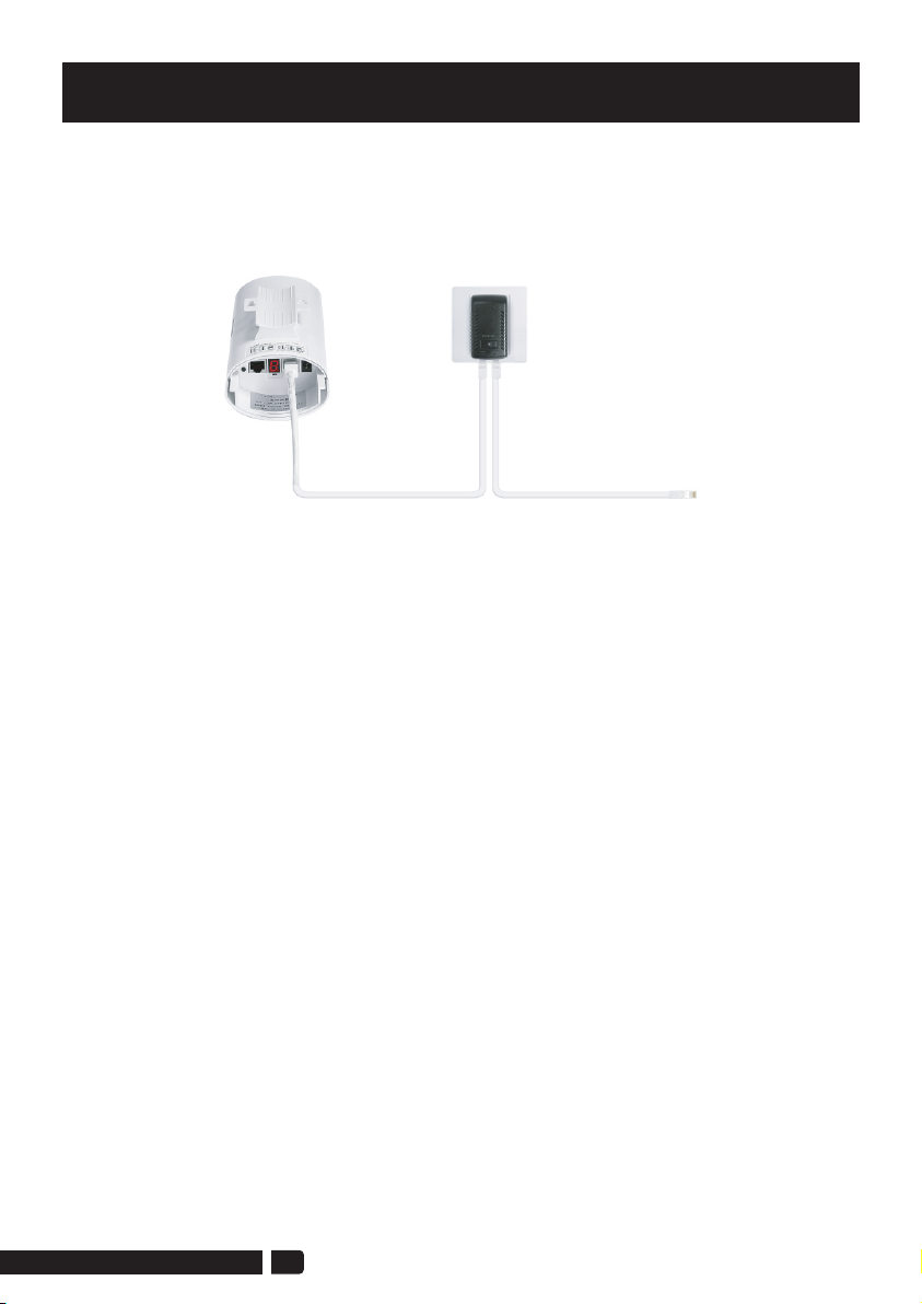
1. Connect the CPE to the computer
Refer to the figure left to connect the CPE to the computer through a PoE
adapter and an Ethernet cable.
POE Charger
POE LAN
PC
AP
09
Tabla de contenidos
Otros manuales de Hardware de red de ULNA


Manuales populares de Hardware de red de otras marcas

Matrix Switch Corporation
Matrix Switch Corporation MSC-HD161DEL Manual de usuario

B&B Electronics
B&B Electronics ZXT9-IO-222R2 Manual de usuario

Yudor
Yudor YDS-16 Manual de usuario

D-Link
D-Link ShareCenter DNS-320L Manual de usuario

Samsung
Samsung ES1642dc Instrucciones de uso

Honeywell Home
Honeywell Home LTEM-PV Instrucciones de montaje


