UAB Aldrea Totem MiniLab Manual de usuario

!
MiniLab User Guide
!
Totem by UAB Aldrea
ver 1.1!

www.totemmaker.net
Totem MiniLab
Table of contents
Introduction 3.........................................................
Who is it for 3......................................................................................................................
What’s in the box 3..............................................................................................................
Overview 4..............................................................
LabBoard 4...........................................................................................................................
TotemDuino 5......................................................................................................................
Using MiniLab 6.....................................................
Powering up 6......................................................................................................................
Measuring voltages 8...........................................................................................................
Setting output voltage 9.......................................................................................................
Digital inputs 11...................................................................................................................
Frequency meter 13.............................................................................................................
Measuring current 14..........................................................................................................
Setting programmable voltage output 16............................................................................
Using pulse counter 18........................................................................................................
Generating pulses 19............................................................................................................
Programming with MiniLab 22..............................
Connecting MiniLab to your computer 22..........................................................................
Using Arduino IDE 23.........................................................................................................
Expanding MiniLab 28...........................................
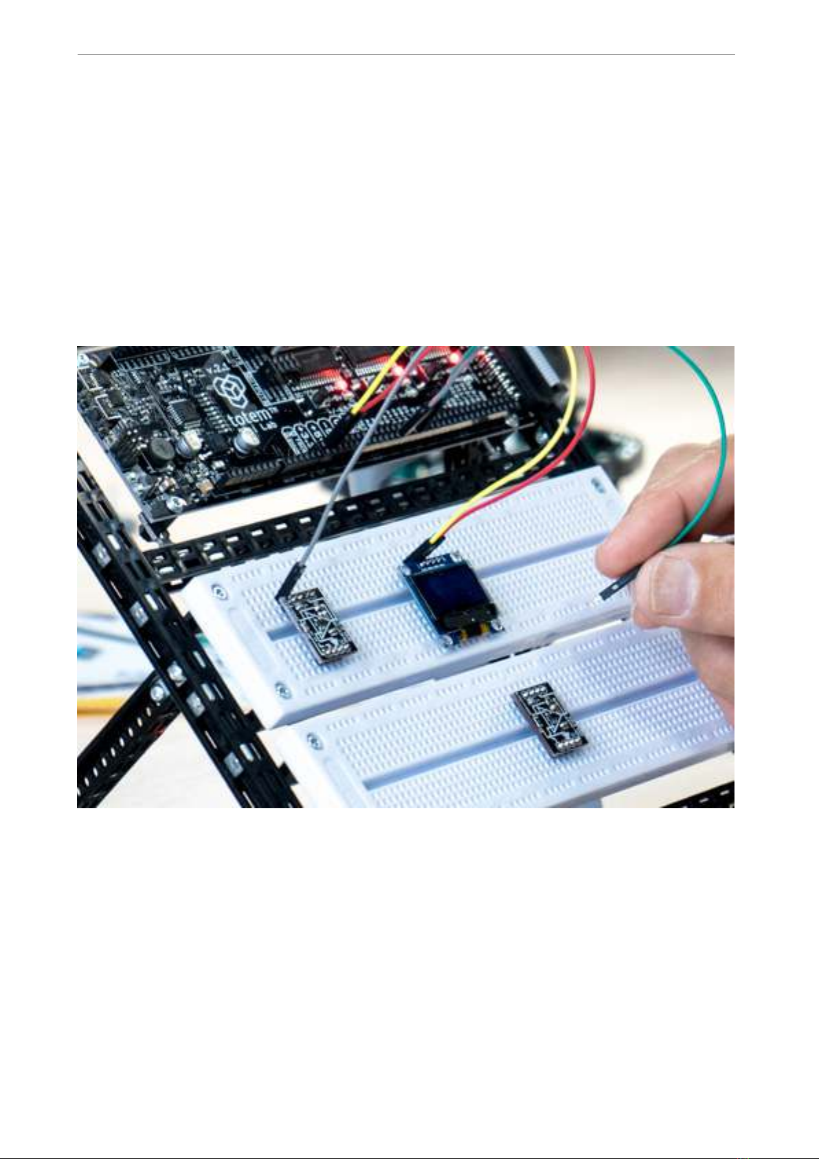
Using breadboards 28.........................................................................................................
Side panels 29......................................................................................................................
What’s next 31.........................................................
!of !231

www.totemmaker.net
Totem MiniLab
Introduction
We at Totem congratulate you on getting your first electronics laboratory! Totem MiniLab
contains all the necessities for starting your path in the world of electronics and
programming. This document will guide you through all the steps in getting to know your
MiniLab, setting it up and learning about all of its capabilities.
Using MiniLab should be simple and fun! While building it, we tried to address and
improve all the negative parts about prototyping — no longer you’ll have to deal with
messy wiring, fragile connections and headaches of where to mount every separate part of
your experiment.
MiniLab is meant to be used together with Totem construction system which allows users
to build solid workbenches with integrated breadboards, as well as available expansion
boards which can expand the capabilities of the MiniLab even further.
Who is it for
Our main goal with MiniLab is to make a platform which would give an easy and
approachable way for students and young makers communities to build up on, using it as
a stepping stone into the world of electronics and programming.
While not intended to be used in place of a professional level equipment, MiniLab has its
own advantages — small size, speed of setup and versatility could find its place in any
makers shop.
What’s in the box
In the MiniLab kit you’ll find:
•TotemDuino - our improved version of Arduino UNO platform,
•LabBoard - a capable experimentation and measuring platform,
•34-pin flat cable — use it to connect TotemDuino and LabBoard together,
•Collection of Totem construction parts — for building Totem workbench.
• Voltage adapter — to power MiniLab from the mains,
• Breadboards — to extend your experimentation area,
• Breadboard cables — short male to male cables useful for experimentation,
• Building instructions — suggested use of Totem parts for building a workbench
where everything neatly mounts together.
!of !331

www.totemmaker.net
Totem MiniLab
Overview
MiniLab at its core consists of two main parts - LabBoard and TotemDuino. In this
chapter, their main attributes are presented together with a quick feature list. While the
best functionality is achieved when using them together connected via supplied flat cable,
they can fully function on their own, keeping in mind that some functionality such as
TotemDuino connections will not be available without main TotemDuino board.
LabBoard
!
Fig. 1 MiniLab board overview
This board has a dual use — firstly it can be used as an expansion board to the
TotemDuino system, offering easily accessible input and output connections, and secondly
— it is a measuring and testing unit, containing such modules as:
•Digital to Analog converter — a 3 channel, 12 bit converter, capable of outputting a
pre-set voltage in the 0-2.5V range.
•Voltage measure — three inputs in the +-0.5 V, +-5V and +-50V range.
•Current measure — sensing current up to 800 mA.
•Frequency meter — digital signal frequency measurement module, capable of signals
up to 1 MHz.
•Pulse counter — digital signal pulse counter, counting up to 999999999 pulses in a
signal.
•Pulse generator — unit capable of generating finite or infinite series of pulses, with
programmable pulse width and period.
!of !431

www.totemmaker.net
Totem MiniLab
TotemDuino
!
Fig. 2 TotemDuino board
TotemDuino expands upon the great Arduino UNO platform idea. While it is kept fully
backwards compatible with Arduino, a lot of additional features are included as well, such
as:
•Output protection — nothing limits creativity as the fear of making a mistake and
breaking something. TotemDuino comes with all of its output pins going into LabBoard
protected against over-voltage or short-circuit conditions. No experiment could go
wrong this way!
•Expansion port — a 34 pin flat-cable connection connects to the LabBoard for easy
pin access.
•Powerful 5 V regulator — you'll be less likely to run out of power while
experimenting with higher power loads such as motors.
•Selectable microcontroller logic voltage — as the world progresses from 5 V
towards 3.3 V logic voltage, TotemDuino can work with both just by the flip of a switch,
without the need for any additional adapters or converters.
!of !531
www.totemmaker.net
Totem MiniLab
Using MiniLab
In this chapter all of the main features of the MiniLab are explained and a usage example
is provided for each of intended use-case. Features discussed here do not affect
TotemDuino, and work independently from it, so no matter what code or experiment
you’re working on at a given time, all of the LabBoard features are still available to use.
If used together with suggested Totem construction system, MiniLab is mounted in the
workbench style system, which allows easy access to all of available pins, as well as
breadboard work area.
Fig. 3 An ongoing experiment on MiniLab workbench
Powering up
MiniLab comes with a 12 V, 1.5 Amp external power supply. Internally, supply voltage is
then regulated into several voltages needed to run various parts of the system. Each of
these can be used during measurements or experiments, as they do have easily accessible
pins that equipment can be connected to.
While MiniLab can easily use any of the available voltage for your experiments, digital
signals going to and from TotemDuino shouldn’t be higher than the currently selected
!of !631

www.totemmaker.net
Totem MiniLab
running voltage for it. A selector switch on the TotemDuino board can set the supply
voltage for the TotemDuino microcontroller either at 5 or 3.3 volts. This allows you to set
the logic level interfacing with various external equipment that could only be used at one
of these voltages without any additional voltage level converters. Refer to TotemDuino
section for explanation on how to set the voltage.
Voltages that are available to use are:
• 12 V, 1.0 A — direct supply voltage,
• 5 V, 0.5 A — regulated supply voltage, shared with TotemDuino,
• 3.3 V, 0.25 A — regulated supply voltage, shared with TotemDuino and LabBoard
processor,
• -5 V, 0.5 A — separate regulated voltage, for experimentation with operation amplifiers,
•0..3.3 V programmable regulated voltage output, up to 0.35 A.
A power supply schematic is provided for reference:
!
Fig. 4 Power regulators in MiniLab
It is possible to run only from USB power, but in that case modules relying on higher
voltage, such as programmable regulator will not be available.
!of !731

www.totemmaker.net
Totem MiniLab
Measuring voltages
LabBoard has a 3 channel voltage measurement module. Each has a pre-set measurement
range:
• ± 0.5 V - best to be used when measuring small scale signals when maximum precision
is required.
• ± 5 V - for measuring TTL logic level signals.
• ± 50 V - for external signal measuring.
Left display is used in the LabBoard for showing currently measured voltage. Currently
active channel is selected with a button under the display, and the current active channel
LED lights up.
Display shows value in millivolts when using ± 0.5 V channel, otherwise the output is in
Volts. Blinking display indicates that currently measured voltage is negative.
!
Fig. 5 Voltage measuring module
Example
1. Connect the ± 5 V input with a 3.3 Volt output.
!of !831

www.totemmaker.net
Totem MiniLab
2. Press the channel selector button until the ± 5 V input LED lights up.
3. Observe the display — it should indicate a value close to 3.3 Volts:
!
Fig. 6 Measuring one of the supply voltages
Setting output voltage
Using inbuilt 3 channel Digital to Analog Converter (DAC) allows you to output any
voltage in the 0..3V range, at up to 15 mA current. This is useful for experimenting with
comparators or operational amplifiers, as they need various reference or input voltages.
!of !931

www.totemmaker.net
Totem MiniLab
!
Fig. 7 Programmable output voltage
Middle display is used for showing the current output voltage for the active channel,
which itself is indicated by the middle column of LED’s. Pressing middle SELECT button
allows you to change the active channels. To edit currently preset voltage, SELECT button
must be held until LED starts blinking. Then SET+ and SET- buttons can be pressed to
adjust currently selected channels voltage. All other inactive channels still keep the same
preset voltage until it’s changed by SET buttons on the side of the board.
Example
1. Connect the DAC1 output to the ± 5 V voltage measuring channel input.
2. Using middle select button switch the current output channel until DAC1 Out LED
lights up.
3. Using left select button switch the measure channel to ± 5 volts.
4. Hold SELECT button until DAC1 Out LED starts to blink.
5. Using Set+ and Set- button change the output value of the DAC1 channel.
6. Observe that voltage measure display follows the same value as the DAC output one.
!of !10 31
Este manual sirve para los siguientes modelos
2
Tabla de contenidos
Manuales populares de Robótica de otras marcas

STEMCenter USA
STEMCenter USA Pi-Bot v2.00 Manual de usuario

SunFounder
SunFounder PiDog Manual de usuario

Universal Robots
Universal Robots UR5 Manual de usuario

Universal Robots
Universal Robots E Series Manual de usuario

YASKAWA
YASKAWA MOTOMAN-MPL80 II Manual de usuario

EFORT
EFORT ECR5 Manual de instrucciones


