Step 1: Insert the bottom edge of the TR-CONTROL-6 module down into a
rear slot of the chassis.
Step 2: Carefully swing the upper edge of the board towards the back of the
chassis until it touches the short standoff attached to the chassis.
Step 3: Align the long standoff with the short standoff and tighten.
2
3
1
Step 1: Insert the bottom edge of the TR-CONTROL-6 module down into a
front slot of the chassis.
Step 2: Carefully swing the upper edge of the board towards the back of
the chassis until it touches the 1¼" (31.75mm) standoffs installed
on the rear module.
Step 3: Align two 4-40 screws with the two standoffs and tighten.
Step 4: Address and wire the modules according to the instructions in this
manual.
WIRING
NOTE: All wiring must conform to applicable local codes, ordinances, and
regulations.
1. Install module wiring in accordance with the job drawings and appropri-
ate wiring diagrams.
2. All wiring to the TR-CONTROL-6 is done via terminal blocks. In order to
properly make electrical connections strip approximately ¼" (6.4 mm)
of insulation from the end of wire, sliding the bare end of the wire under
the clamping plate screw.
3. Set the address on the modules per the job drawing. Use the rotary code
switches to set the address of the first module between 01 and 94 (or 01
and 154 for panels that support 159 addresses).
To select Class B operation, install the J1 Shunt. The remaining modules are
automatically assigned to the next five higher addresses. For example, if the
base address switch is set to 28, the next five modules will be addressed to
29, 30, 31, 32, and 33.
To select Class A operation, remove the J1 Shunt. A maximum of three Class
A circuits are available. For example, if the base address switch is set to 28, 30
and 32 will be automatically assigned to the modules while 29, 31 and 33 are
available to be used for other modules on the SLC. For Class A and B opera-
tion, DO NOT set the lowest address above 94(or 154 for panels that support
up to 159 addresses), as the other modules will be assigned to nonexistent
addresses.
4. A shunt is provided to disable a maximum of three unused modules.
(See Figure 5.) Modules are disabled from the highest address and work
downward. If two modules are disabled, the lowest four addresses will
be functional, while the highest two will be disabled. For example, if
the shunt for Address Disable is placed on “two” and the base address
switch is set to 28, the modules will be assigned to 28, 29, 30 and 31,
disabling the highest two positions.
NOTE: In Class A operation, placing the small shunt on “disable 3” will dis-
able all three addresses. Placing the small shunt on “disable 2” will disable
two out of the three addresses. For example, if the address switch is set to 28
and the small shunt is placed on “disable” 2, addresses 30 and 32 will be dis-
abled while address 28 will be enabled. The TR-CONTROL-6 must have power
cycled for shunt changes to take effect.
C0226-00
FIGURE 4B. INSTALLATION OF TR-CONTROL-6 MODULE IN FRONT
CHASSIS POSITION
5. There is an active short circuit protection option for each address. The
board is shipped with this option disabled for each address represented
by six large shunts on the “Disable Short Circuit Protection” area. To
enable short circuit protection for an address, remove the corresponding
shunts on the “Disable Short Protection” area. When enabled, this option
will isolate a short occurring on any active circuit allowing the remaining
circuits to continue normal operation.
NOTE: All references to power limited represent “Power Limited (Class 2)”.
NOTE: Short circuit protection may only be enabled if power supply monitor-
ing is enabled.
NOTE: Place unused shunts on single pin to store on board for future use.
NOTE: Power must not be applied to the unit when changing functionality of
the shunts.
NOTE: Whether in Class B or Class A wiring, power supply monitoring and
short circuit protection must be enabled on the NAC circuits that are sharing
a power supply.
NOTE: Short circuit protection can only be disabled if a power supply is not
being shared by multiple NACs.
ENABLE POWER SUPPLY MONITOR
DISABLE SHORT CIRCUIT PROTECTION
SYNC GENERATOR
A/B SELECT
DISABLE 1
DISABLE 2
DISABLE 3
J1 SHUNT
SIDE VIEW:
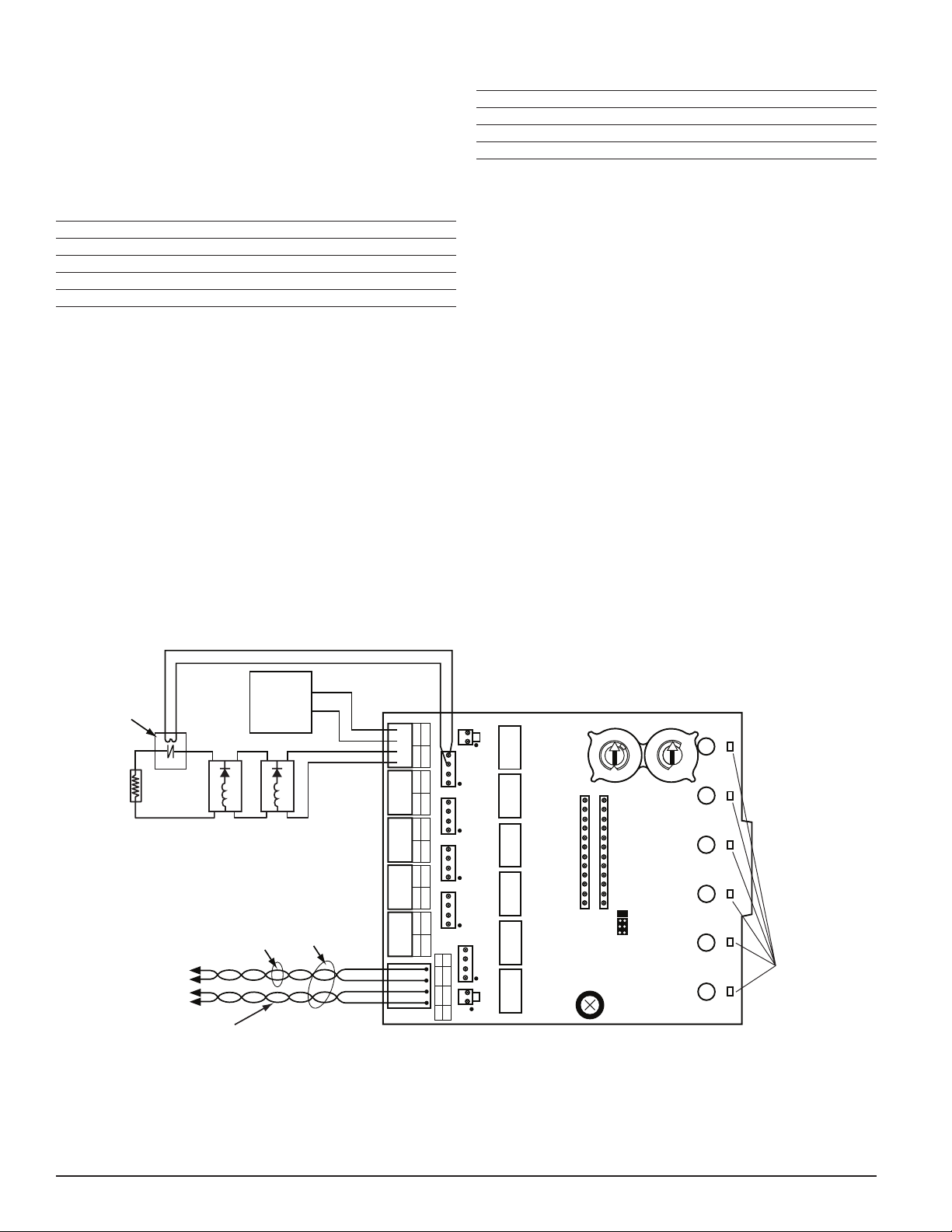
NOTIFICATION APPLIANCE/
SLC WIRING
TERMINAL
C0174-00
FIGURE 5.
NOTE: SLC wiring is the top terminal block, notification appliance/power
supply is the bottom.
WIRING NOTES
• Power-limited circuits must employ type FPL, FPLR, or FPLP cable as
required by Article 760 of the NEC.
• For easier wiring, assign all power-limited wiring to one side of the en-
closure rather than alternating with non power-limited.
PROGRAMMING
The modules are programmed as devices in each system according to the pro-
gramming instructions in the appropriate FACP manual.
NAC WIRING AND SUPERVISION
For Class B applications (figures 6 and 7 are typical): connect the positive ter-
minal of the notification appliance(s) to the NAC+ terminal and the negative
device terminal to the adjacent NAC- terminal. Connect one (for each NAC)
of the supplied EOL resistors across the NAC+ and NAC- wires, at the ends
farthest away from the NAC terminal of the TR-CONTROL-6.
For Class A applications (figures 8 and 9 are typical) wire the NACs per Table 2.
The A/B select shunt must be removed prior to connecting the TR-CONTROL-6
to the SLC. The EOL resistors should not be used. The TR-CONTROL-6 is ca-
pable of supporting 3 Class A NACs. The TR-CONTROL-6 will only respond
at the base address, base address +2, and base address +4 (assuming no
addresses have been disabled).
TABLE 2.
NAC# (+) CONNECTIONS (–) CONNECTIONS
+0 +0 NAC+, +1 NAC+,
Notification Appliance+
+0 NAC–, +1 NAC–,
Notification Appliance–
+2 +2 NAC+, +3 NAC+,
Notification Appliance+
+2 NAC–, +3 NAC–,
Notification Appliance–
+4 +4 NAC+, +5 NAC+,
Notification Appliance+
+4 NAC–, +5 NAC–,
Notification Appliance–
3 I56-6976-000
2/1/2021