touch bionics i-limb Manual de usuario

i-limbTM ultra revolution
Clinician Manual
Part number: MA01140: Issue No. 1, April 2013

2
This symbol signies important information and is used throughout the manual.
This document provides instruction for prosthetists in the tting and servicing of the i-limb ultra revolution
and should be read in full prior to tting. It is highly recommended that the use of this manual is made in
conjunction with instruction from a clinician experienced in upper limb and myoelectric prostheses.
A separate USB datadrive is included with your kit that contains all relevant product manuals.
You may also refer to www.touchbionics.com to ensure the latest copy of this document.

3 of 57
Part number: MA01140: Issue No. 1, April 2013
2
Table of Contents
1. i-limb ultra revolution 1.1 Product Description
1.2 Prosthesis Overview
2. Socket 2.1 Control Sites
2.2 Socket Fabrication
2.3 Charge Port Placement Assembly
2.4 Battery Options
2.5 Battery Conguration
2.6 Battery Installation
2.7 Battery Charging
3. Wrist 3.1 Wrist Connection Options
3.2 Quick Wrist Disconnect (QWD)
3.3 Wrist Disarticulation
3.4 Flex Wrist
3.5 Multi-ex Wrist
4. Adjustments 4.1 Digit Conguration
4.2 Digit Installation
4.3 Thumb Installation
5. Covers 5.1 Cover Options
5.2 Donning the i-limb skin active Cover
5.3 Dong the i-limb skin active Cover
5.4 Donning the i-limb skin natural Cover
5.5 Dong the i-limb skin natural Cover
5.6 Wear and Care Guidelines
6. biosim 6.1 biosim Overview
6.2 biosim Connecting
6.3 Navigating biosim
6.3.1 Myotesting
6.3.2 Control Strategy
6.3.3 Features
6.3.4 Training
6.3.5 Hand Health Check
6.3.6 Usage
6.3.7 Exit
7. Support Information 7.1 Storage and Maintenance
7.2 Troubleshooting
7.3 Warnings and Precautions
8. User Information 8.1 User Details
9. Appendix 9.1 Technical Information
9.2 i-limb ultra revolution Information
9.3 Component Compatibility
9.4 Warranty

4 of 57
Part number: MA01140: Issue No. 1, April 2013
1.1 Product Description
The i-limb ultra revolution is an externally powered, multi-
articulating prosthetic hand which oers a range of features
beyond the functions of the traditional prosthetic hand.
Individually motorized digits and thumb, stall detection and the
unique biosim software used to control the i-limb ultra revolution
result in the most versatile prosthetic hand currently available to
the global market.
Users can choose from a wide selection of automated grips and
gestures to help complete daily tasks. Grips and gestures can
then be customized further for precise control.
The i-limb ultra revolution oers compliant grip through indi-
vidually powered digits with stall out ability. A powered rotating
thumb in conjunction with a pulsing, enhanced grip (vari-grip),
an anti-drop safety feature (auto-grasp) and the wide range of
automated grip patterns lead to broad functionality.
1.2 Prosthesis Overview
The i-limb ultra revolution is available in either black or neutral
colors, as well as small or medium sizes. The hand serial number is
positioned proximal to the base of the thumb on the connection
plate. The serial number should start with a “R” and be followed by
four numbers (also highlighted in biosim, see section 6).
1.0 i-limb ultra revolution

4 of 57 5 of 57
Part number: MA01140: Issue No. 1, April 2013
Motorized Digit
Knuckle
Palmar Fairing
Motorized Thumb
On / O Switch
6 of 57
Part number: MA01140: Issue No. 1, April 2013
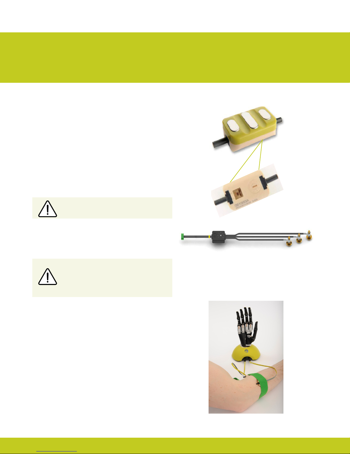
2.1 Control Sites
One option for control of the i-limb ultra revolution is electrodes.
There are two electrode options available for use with the i-limb
ultra revolution, compact electrodes (g. 1) or remote electrodes
(g. 2). For information regarding the tting of the Touch Bionics
Electrode, review the manual provided with the electrode.
Electrode Site Selection
The use of virtu-limb, the Touch Bionics’ myotesting system, is
recommended to determine the optimal placement of electrodes
(g. 3).
Consult Touch Bionics training materials for information on myo-
testing or section 6 of this manual for information on myotesting
within biosim.
2.2 Socket Fabrication
While fabricating the socket for the i-limb ultra revolution, special
considerations will need to be given to:
1. Battery placement, size and conguration
2. Electrode position or other control method
3. Charge port placement
4. Socket length and the overall length of the prosthesis in
comparison to the opposite side.
Clinicians should have prior experience with building externally
powered prosthetic sockets before tting the i-limb ultra revolution.
Touch Bionics’ batteries, charger port and switch block components
should always be used with the i-limb ultra revolution.
Do not rely on previous myoelectrical testing.
Use anatomical sites where the electrode will
maintain constant, even contact with the skin. Avoid
placing electrodes near socket interface trim lines,
bony areas, skin grafts or fatty tissue.
2.0 Socket
Figure 1. Electrode Options
Figure 3. virtu-limb
Figure 2. Remote Electrode

6 of 57 7 of 57
Part number: MA01140: Issue No. 1, April 2013
Socket Material
Coupling Piece Assembly
Insert the castelation ring (coupling
piece) into lamination ring and turn
until seated. Insert retaining ring
around outside edge of coupling
piece and use QWD release tool to
seat the retaining ring. The
QWD release tool is available to
order from Touch Bionics.
Please reference part number
PL091084 when ordering.
The use of Carbon ber is not recommended due to
electrical conductivity, if it is required to improve strength
then the carbon ber lamination must be grounded, if used
directly adjacent to electrodes (see Page 6). Please contact
Touch Bionics to order modied electrodes.

8 of 57
Part number: MA01140: Issue No. 1, April 2013
Use Velcro™ to position the batteries on the pre-prepared
at surfaces to prevent distortion.
Consideration of battery placement is particularly important
in longer sockets. The shape of the inner socket must also be
considered.
If the residual limb is long, wrist disarticulation or bulbous, the
position of the battery dummies and charge port are best placed
midway up the arm along the inner socket ensuring they will not
impact the ability to don/do the prosthesis and that the posi-
tion will not result in pressure from the residual limb that could
distort the battery.
Placement of batteries should allow for removal of the inner
socket.
If the socket has a bulbous distal end, do not position batteries or
charger port around the narrow region of the prosthesis.
Battery Placement
Battery Placement for a Long Residual Limb

8 of 57 9 of 57
Part number: MA01140: Issue No. 1, April 2013
Create a drill hole of 8.0mm through the inner surface of the
prosthetic frame. Ensure a at surface has been created to
accommodate the charge port mounting frame (if installing a
switch block as an alternative to the charger port, create a drill
hole to cater for the panel mount).
Smooth the edges of the drill hole and insert the threaded
charge port. A minimum thread height of 3.2mm above the
socket surface is required for full engagement of washers and
locking nut.
Position the M8 Lock Washer and the M8 Flat Washer before
hand tightening the the locking nut.
Use a 3/8” wrench to tighten the locking nut. Do not overtighten.
Do not use pliers on the charge port.
Position the M8 Lock Washer and M8 Flat
Washer in place over the threaded shaft of the
charger port. Engage the M8 locking nut with
the threaded shaft and tighten rmly by hand.
The use of both the Lock Washer and Flat
Washer is vital to ensure the charge port is not
damaged by over tightening.
It is important to provide sucient space for the charge port
between the inner and outer sockets. The charge port should be
positioned so that it is unaected by forces running through the
socket to prevent damage.
2.3 Charge Port Placement Assembly

10 of 57
Part number: MA01140: Issue No. 1, April 2013
i-limb 1,300 mAh Battery i-limb 2,000 mAh Battery
Capacity 1,300 mAh 2,000 mAh
Battery Dimensions
Length 70mm (2.76”) 80mm (3.17”)
Width 35mm (1.39”) 44mm (1.74”)
Height 6mm (0.24”) 7.5mm (0.30”)
Dummy Battery
Dimensions
Length 69mm (2.77”) 87mm (3.48”)
Width 35mm (1.39”) 45mm (1.80”)
Height 10mm (0.39”) Single cell
16mm (0.63”) Dual cell
11mm (0.44”) Single cell
19mm (0.76”) Dual cell
Application Moderate Use Heavy Use
Part Number 000019 000231 Single cell
000232 Dual cell
DC Socket SA000229 SA000234
Switch Block SA000193 SA000192
Two battery options are available for the i-limb ultra revolution, both of which have been specically designed to meet the power
requirements of the hand. Battery selection should be based on available space within the socket fabrication, shape of the residual limb
and the expected level of use. The corresponding DC socket and switch block will also be required.
2.4 Battery Options
Otros manuales para i-limb
1
Tabla de contenidos
Manuales populares de Robótica de otras marcas

STEMCenter USA
STEMCenter USA Pi-Bot v2.00 Manual de usuario

SunFounder
SunFounder PiDog Manual de usuario

Universal Robots
Universal Robots UR5 Manual de usuario

Universal Robots
Universal Robots E Series Manual de usuario

YASKAWA
YASKAWA MOTOMAN-MPL80 II Manual de usuario

EFORT
EFORT ECR5 Manual de instrucciones


