TOPSCCC EX-96085 Manual de usuario

EX-96085 User Manual 1
EX-96085
(Human Machine Interface)
User Manual
“The Human Machine Interface is where people and technology meet.”
Release Date Revision
Sep 2006 V0.1
®2005 TOPSCCC Technology, Inc. All Rights Reserved. Published in
Taiwan
TOPSCCC Technology, Inc.
5F, NO. 12, ALLEY 345, Yang-Guang ST. , Nei-Hu, Taipei, Taiiwan R.O.C
Tel:886-2-27999080 Tel:886-2-26585042, 26575516 E-mail: support@topsccc.com URL:
www.topsccc.com

EX-96085 User Manual 2
Warning!___________________________________
Disclaimer
This information in this document is subject to change without notice. In no event shall
TOPSCCC Technology Inc. be liable for damages of any kind, whether incidental or
consequential, arising from either the use or misuse of information in this document or in any
related materials.
This equipment generates, uses and can radiate radio frequency energy and if not installed and
used in accordance with the instructions manual, it may cause interference to radio communica-
tions. It has been tested and found to comply with the limits for a Class A computing device
pursuant to FCC Rules, which are designed to provide reasonable protection against such
interference when operated in a commercial environment. Operation of this equipment in a
residential area is likely to cause interference in which case the user at his own expense will be
required to take whatever measures may be required to correct the interference.
Electric Shock Hazard – Do not operate the workstation with its back cover removed. There are
dangerous high voltages inside.

EX-96085 User Manual 3
Table of Contents______________________
Warning!…………………………………………………………………………….……..….2
Disclaimer………………………………………………………………….…………………2
Chapter 1 Introduction
1.1 Features .............................................................................................................6
1.2 Specifications .....................................................................................................6
1.3 Dimensions ........................................................................................................8
1.4 Block Diagram....................................................................................................9
1.5 Mainboard ..........................................................................................................9
1.6 Brief Description of the EX-96085....................................................................12
Chapter2 SystemInstallation
2.1 Installation of the EX-96085 .............................................................................13
Chapter3 MainboardConfiguration
3.1 JUMPER & CONNECTOR QUICK REFERENCE TABLE ...............................16
3.2 COMPONENT LOCATIONS ............................................................................17
3.3 HOW TO SET THE JUMPERS ........................................................................18
3.4 COM 1 RI & VOLTAGE SELECTION ...............................................................20
3-5. COM 2 RI & VOLTAGE SELECTION..............................................................20
3-6. COM 3 RI & VOLTAGE SELECTION..............................................................20
3-7. COM 4 RI & VOLTAGE SELECTION..............................................................20
3.8 RS232/422/485 (COM2) SELECTION .............................................................24
3.9 BRIGHTNESS VOLTAGE SELECTION ...........................................................25
3.10 LVDS VOLTAGE SELECTION .......................................................................25
3.11 LVDS PANEL RESOLUTION SELECTION ....................................................26
3.12 CMOS FUNCTION SELECTION ...................................................................26
3.13 RESET / NMI SELECTION ............................................................................27
3.14 CPU_VCCA VOLTAGE SELECTION .............................................................27
3.15 CPU FREQUENCY SELECTION...................................................................28
3.16 COM PORT CONNECTOR............................................................................28
3.17 VGA CONNECTOR........................................................................................31
3.18 LVDS CONNECTOR......................................................................................32
3.19 POWER CONNECTOR .................................................................................33
3.20 HARD DISK DRIVE CONNECTOR................................................................34
3.21 PRINTER CONNECTOR ...............................................................................35
3.22 LAN CONNECTOR ........................................................................................36

EX-96085 User Manual 4
3.23 LAN LED CONNECTOR ................................................................................36
3.24 KEYBOARD CONNECTOR ...........................................................................37
3.25 PS/2 MOUSE CONNECTOR .........................................................................37
3.26 HDD LED CONNECTOR ...............................................................................38
3.27 POWER BUTTON..........................................................................................38
3.28 POWER LED CONNECTOR .........................................................................38
3.29 UNIVERSAL SERIAL BUS CONNECTOR.....................................................39
3.30 MEMORY INSTALLATION .............................................................................41
3.31 INVERTER CONNECTOR.............................................................................41
3.32 POWER MODULE .........................................................................................42
3.33 COMPACT FLASH CONNECTOR.................................................................43
3.34 PCI-104 CONNECTOR..................................................................................44
3.35 CPU FAN CONNECTOR ...............................................................................45
3.36 SYSTEM FAN CONNECTOR ........................................................................46
3.37 SERIAL ATA CONNECTOR ...........................................................................46
3.38 RESET & SPEAKER CONNECTOR..............................................................47
Chapter 4 Software Utility
4.1 Introduction to Software Utilities.......................................................................48
4.2 VGA DRIVER UTILITY.....................................................................................48
4.3 FLASH BIOS UPDATE.....................................................................................49
4.4 LAN DRIVER UTILITY .....................................................................................50
4.5 SOUND DRIVER UTILITY ...............................................................................51
4.6 INTEL® C HIPSET SOFTWARE INSTALLATION UTILITY .............................52
4.7 USB2.0 SOFTWARE INSTALLATION UTILITY ...............................................53
4.8. SERIAL ATA DRIVER UTILITY .......................................................................54
4.9 WATCHDOG TIMER CONFIGURATION .........................................................55
Chapter 5 AWARD BIOS Setup
5.1 Introduction to Award Bios Setup .....................................................................56
5.2 ENTERING SETUP..........................................................................................56
5.3 THE STANDARD CMOS FEATURES..............................................................58
5.4 THE ADVANCED BIOS FEATURES ................................................................62
5.5 ADVANCED CHIPSET FEATURES .................................................................64
5.6 INTEGRATED PERIPHERALS ........................................................................66
5.7 POWER MANAGEMENT SETUP....................................................................69
5.8 PNP/PCI CONFIGURATION............................................................................70
5.9 PC HEALTH STATUS.......................................................................................72
5.10 FREQUENCY CONTROL ..............................................................................73
5.11. LOAD FAIL-SAFE DEFAULTS ......................................................................73
5.12. LOAD OPTIMIZED DEFAULTS.....................................................................74

EX-96085 User Manual 5
5.13. PASSWORD SETTING .................................................................................74
5.14 SAVE & EXIT SETUP.....................................................................................75
5.15 EXIT WITHOUT SAVING ...............................................................................75
Chapter6 TouchDriverInstallation
6.1 Introduction to the TB-31 Touch Screen Controll Board………………….……..77
6.2 Configuring the PenMount Windows 2000/XP Driver.......................................81
6.3 Uninstall the PenMount Windows 2000/XP Driver ...........................................88
6.4 Software Functions ..........................................................................................89
Appendix: Mainboard Technical Summary 91

EX-96085 User Manual 6
Chapter1 Introduction
1.1 Features
zHigh performance Celeron M/Pentium M CPU support
z8” SVGA TFT LCD with high luminance
zLow power consumption with fanless cooling system
zNEMA 4/IP 65 compliant front panel
zPanel mount and VESA 75 mounting support
zResistive touch screen
zDC 11~28V wide range power input
zSupport Windows 2000/XP, XP embedded and CE.NET
1.2 Specifications
System
CPU:
Celeron M 600MHz or 1.0GHz without L2 cache
System Memory:
256MB up to 1GB DDRAM
Slot:
One 40GB HDD, One compact flash drive (optional)
Power Supply:
Input voltage range of 10.8~28V
Touch Screen:
Touch screen with 4-wire, analog resistive; resolution of 800 x 600,
light transmission of above 80%; and life of 1 million activations (minimum)
I/O Connectors:
Serial ports: 2 (COM1: RS-232, COM2: RS232/422/485, COM3: reserved, COM4: for touch screen)
Ethernet port (10/100 base-T) x 1;
USB port) x 2,
Parallel port x 1;
Stereo audio mic-in, line-in and line-out x 1;
PS/2 keyboard x 1; and
PS/2 mouse x 1
EMC:
FCC, CE Class A certified

EX-96085 User Manual 7
Display
Resolution, color, and luminance:
8 inches TFT LCD with resolution of 800x600, 262k colors, 400 cd/m2
Mechanical
Construction:
Metal allow housing
Color:
Black front panel
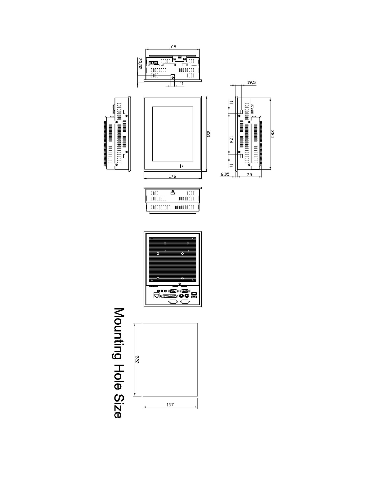
Dimensions:
231(W) x 81(D) x 176(H)mm
Weight:
1.4 kg
Environment
Operating temperature:
0~50 C°
Storage temperature:
0~70°C
Relative humidity:
10~95% @ 40°C non-condensing
Vibration:
5~17Hz, 0.1” double amplitude displacement
17~640Hz, 1.5G acceleration peak to peak
Shock:
10G acceleration peak to peak (11 millimeters)
EX-96085 User Manual 8
1.3 Dimensions
Figure 1.1: Dimensions of the EX-96085
EX-96085 User Manual 9
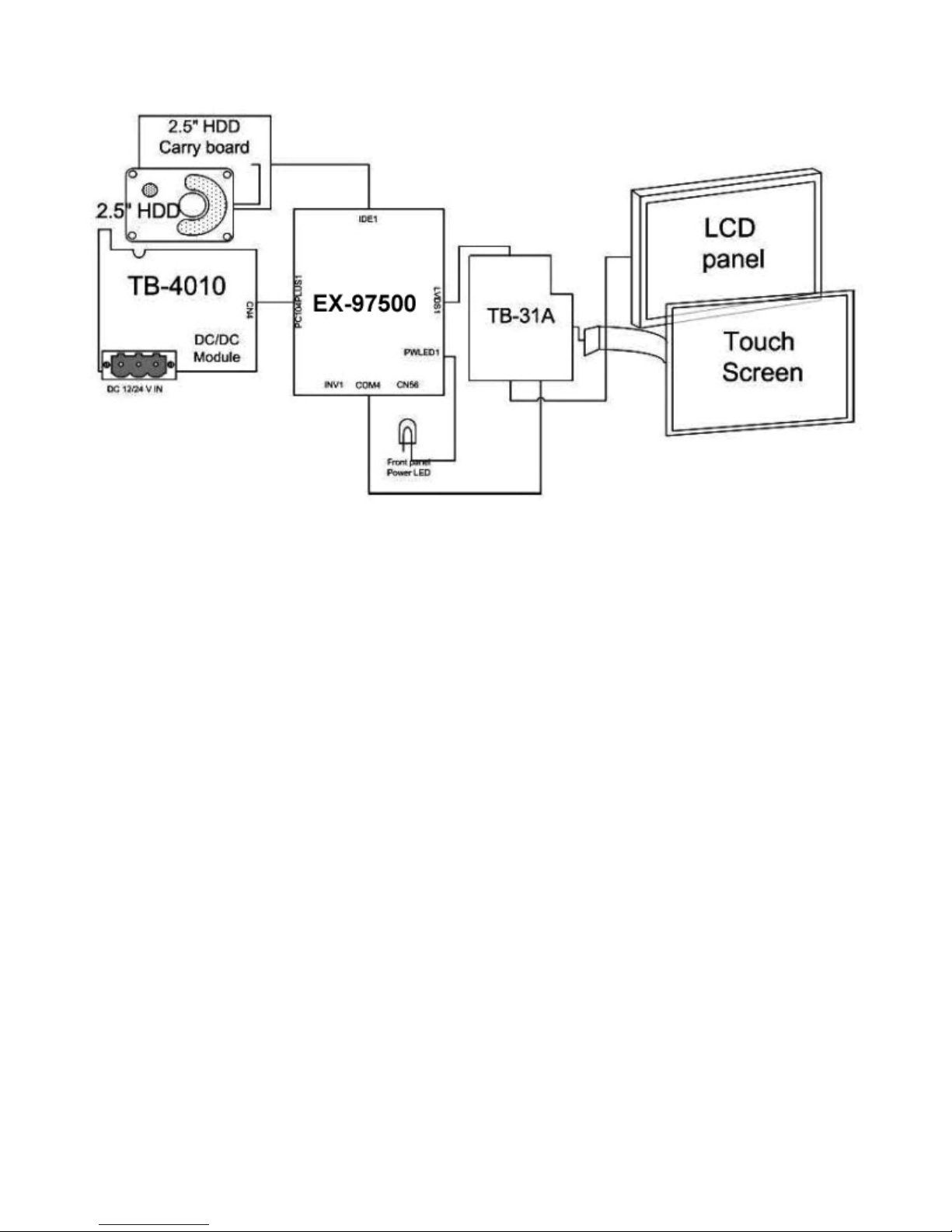
1.4 Block Diagram
Figure 1.2: Block Diagram of the EX-96085
1.5 Mainboard
Specifications
CPU:
Socket 478 Intel Celeron® M up to 1.0GHz Auto detect voltage regulator.
Chipset:
Intel® 855GME+ICH4
DRAM:
One 200-pin DDRAM SO-DIMM up to 1GB
Cache:
Built-in CPU
BIOS:
Phoenix-Award Flash BIOS for plug & play function. Memory size with 4MB and with VGA BIOS.

EX-96085 User Manual 10
Support S I/O Setup
IDE Interface:
One EIDE (UDMA-33/66/100) support 2 IDE devices, one compact flash type II onboard
Serial Port:
Four high speed 16550 Compatible UARTs with Send / Receive 16 Byte FIFOs.
Parallel Port:
One parallel (SPP/EPP/ECP)
CMOS:
Built-in chipset with external battery
Keyboard and Mouse:
PS/2 (mini DIN connector)
Speaker:
Internal buzzer and external speaker connector
VGA:
Integrated in Built-in Intel 855GME, share system memory, support CRT, LVDS
LAN:
Intel 82541 Chip. RJ-45 jack onboard, Support for 10/100/1000 Base-T Ethernet.
Support Wake-On-LAN function.
Sound:
AC ’97 Codec, ALC202A, with line-in, line-out, mic
USB:
Two USB 2.0
Expansion Bus:
One Mini-PCI
Hardware Monitor:
Voltage, CPU temperature and cooling fan
Green Function:
Controlled by hardware and software
Tabla de contenidos


