TIS IO-AC-4G Manual de usuario

THERMOSTAT WITH 4 PUSH-BUTTON PANEL
TIS IO THERMOSTAT PANEL
INSTALLATION MANUAL
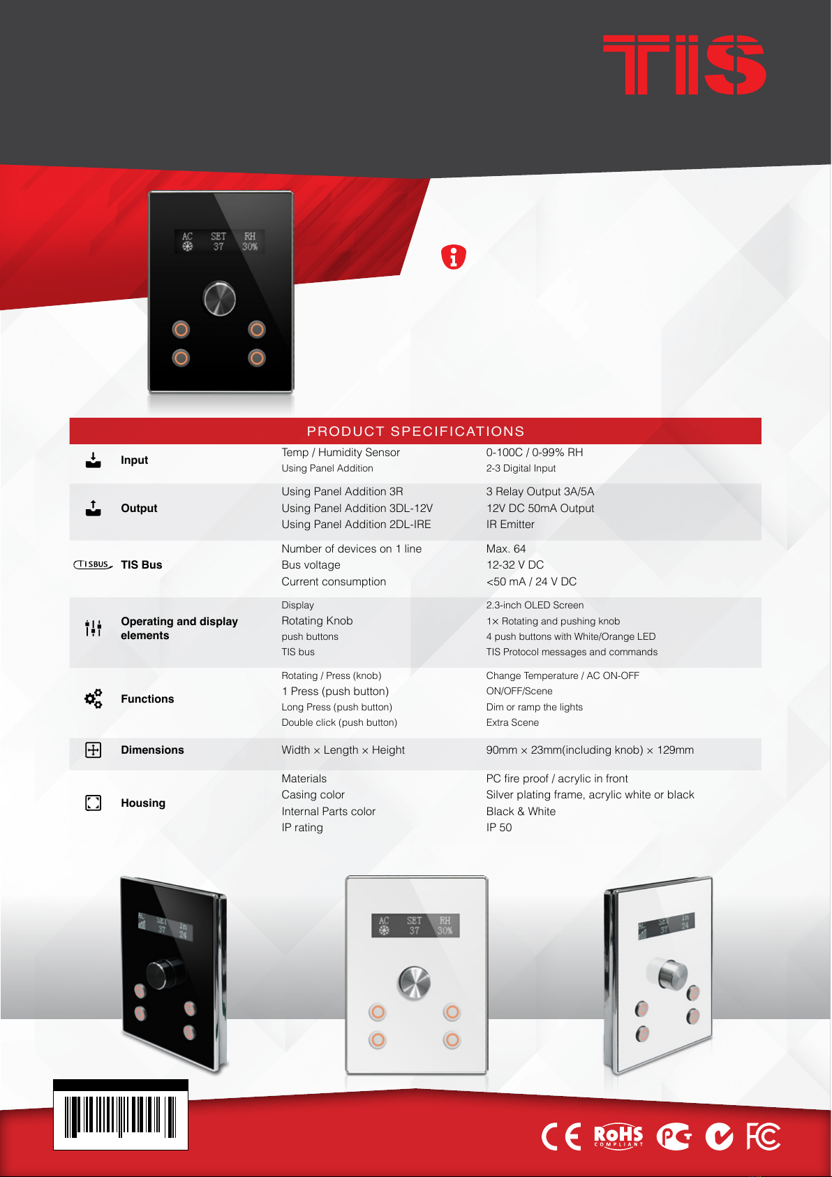
With its elegant shape and design, the IO AC 4G
is available in black or white and includes a stylish
rotating knob for air condition control and 4 push
buttons for lights and shutter control.
Automation Made Easy
Model: IO-AC-4G
BARCODE (UPC-A)
6 58921 80006 5
PRODUCT INFORMATION
PRODUCT SPECIFICATIONS
Input Temp / Humidity Sensor 0-100C / 0-99% RH
Using Panel Addition 2-3 Digital Input
Output
Using Panel Addition 3R 3 Relay Output 3A/5A
Using Panel Addition 3DL-12V 12V DC 50mA Output
Using Panel Addition 2DL-IRE IR Emitter
TIS Bus``
Number of devices on 1 line Max. 64
Bus voltage 12-32 V DC
Current consumption <50 mA / 24 V DC
Operating and display
elements
Display 2.3-inch OLED Screen
Rotating Knob 1×Rotating and pushing knob
push buttons 4 push buttons with White/Orange LED
TIS bus TIS Protocol messages and commands
Functions
Rotating / Press (knob) Change Temperature / AC ON-OFF
1 Press (push button) ON/OFF/Scene
Long Press (push button) Dim or ramp the lights
Double click (push button) Extra Scene
Dimensions Width × Length × Height 90mm × 23mm(including knob) × 129mm
Housing
Materials PC fire proof / acrylic in front
Casing color Silver plating frame, acrylic white or black
Internal Parts color Black & White
IP rating IP 50

INSTALLATION MANUAL
MODEL: IO-AC-4G
TIS CONTROL LIMITED
RM 1502-p9 Easey CommBldg
253-261 Hennessy Rd Wanchai
Hong Kong
TEXAS INTELLIGENT SYSTEM LLC
SUITE# 610. 860 NORTH DOROTHY DR
RICHARDSON
TX 75081.USA
Copyright © 2020 TIS, All Rights Reserved
TIS Logo is a Registered Trademark of Texas Intelligent System LLC in the
United States of America. This company takes TIS Control Ltd. in other
countries. All of the Specifications are subject to change without notice.
www.tiscontrol.com
THERMOSTAT WITH 4 PUSH-BUTTON PANEL
2
Data Cable
Use screened stranded RS485 data cable
with four twisted pairs. Congure devices in
a “Daisy Chain.”
Do not cut or terminate live data cables.
Electrical Wires
The recommended wire size for light
channels is 1.5mm - 2.5mm for loads, if you
are using the Panel Addition 3R type. The
installer should consider the total current
consumption when selecting the wires.
Warranty
There is a two-year warranty provided
by law. The hologram warranty seal and
product serial number are available on
each device.
Read Instructions
We recommend that you read this
Instruction Manual before installation.
Safety instructions
Electrical equipment should only be
installed and tted by electrically skilled
persons.
Failure to follow the instructions may cause
damage to the device and other hazards.
These instructions are an integral part of
the product and must remain with the end
customer.
Programming
This device can be tested and programmed
manually. Advanced programming
requires knowledge of the TIS Device
Search software and instruction in the TIS
advanced training courses.
Simple Installation
You can use 2 screws to install this panel
on wall; it ts on most junction box sizes.
Mounting Location
Install in a dry, indoor area with a suitable
temperature and humidity range.

INSTALLATION MANUAL
MODEL: IO-AC-4G
TIS CONTROL LIMITED
RM 1502-p9 Easey CommBldg
253-261 Hennessy Rd Wanchai
Hong Kong
TEXAS INTELLIGENT SYSTEM LLC
SUITE# 610. 860 NORTH DOROTHY DR
RICHARDSON
TX 75081.USA
Copyright © 2020 TIS, All Rights Reserved
TIS Logo is a Registered Trademark of Texas Intelligent System LLC in the
United States of America. This company takes TIS Control Ltd. in other
countries. All of the Specifications are subject to change without notice.
www.tiscontrol.com
THERMOSTAT WITH 4 PUSH-BUTTON PANEL
3
Insert a large athead screwdriver in
the hole of the Panel Cover. Rotate the
screwdriver 90 degrees.
1
INSTALLATION STEPS
2Separate the Cover, Main Panel, and
Wall Base from each other.

INSTALLATION MANUAL
MODEL: IO-AC-4G
TIS CONTROL LIMITED
RM 1502-p9 Easey CommBldg
253-261 Hennessy Rd Wanchai
Hong Kong
TEXAS INTELLIGENT SYSTEM LLC
SUITE# 610. 860 NORTH DOROTHY DR
RICHARDSON
TX 75081.USA
Copyright © 2020 TIS, All Rights Reserved
TIS Logo is a Registered Trademark of Texas Intelligent System LLC in the
United States of America. This company takes TIS Control Ltd. in other
countries. All of the Specifications are subject to change without notice.
www.tiscontrol.com
THERMOSTAT WITH 4 PUSH-BUTTON PANEL
4
Remove the 2 screws on the Panel Addi-
tion cover.
3
INSTALLATION STEPS
4
Smart Home
Smart Home
Connect the Wall Base and Panel Addi-
tion in this position. Place the upper pins
as shown, and then push the down pins
down with your ngers to assemble.

INSTALLATION MANUAL
MODEL: IO-AC-4G
TIS CONTROL LIMITED
RM 1502-p9 Easey CommBldg
253-261 Hennessy Rd Wanchai
Hong Kong
TEXAS INTELLIGENT SYSTEM LLC
SUITE# 610. 860 NORTH DOROTHY DR
RICHARDSON
TX 75081.USA
Copyright © 2020 TIS, All Rights Reserved
TIS Logo is a Registered Trademark of Texas Intelligent System LLC in the
United States of America. This company takes TIS Control Ltd. in other
countries. All of the Specifications are subject to change without notice.
www.tiscontrol.com
THERMOSTAT WITH 4 PUSH-BUTTON PANEL
5
It should look like this following the cor-
rect assembly.
INSTALLATION STEPS
5
6
Turn off the main electrical source before
installation.
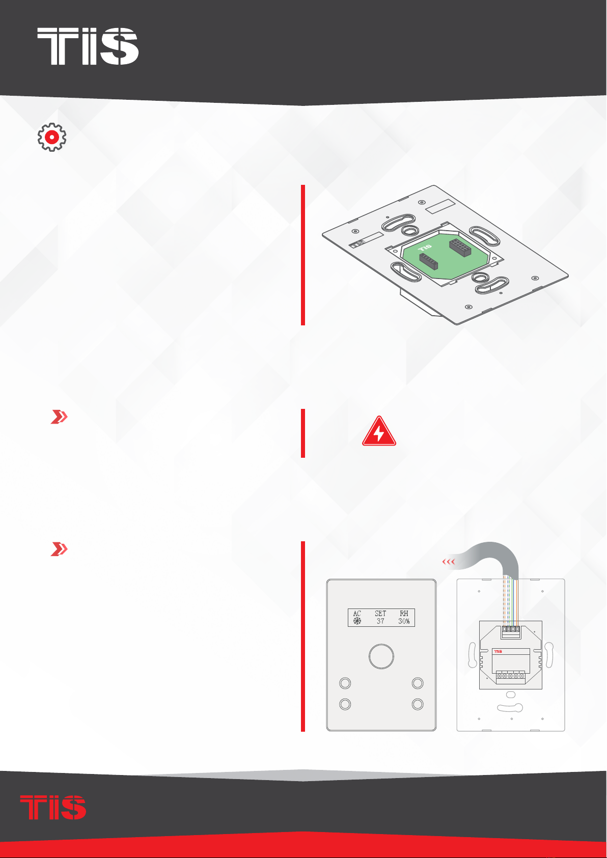
Connect the Cat5e TIS BUS wire to the
Panel Addition.
GND(white-orange)&(white-brown)
D-(white-green)&(white-blue)
D+(blue-green)
+24V(brown-orange)
Cat5e connection
PANEL ADDITION
3 Output Relay 5 Amp
Model : ADD-3R-5A
TIS BUS Input : 45-75mA/24V DC
Output Current : 3A220VAC
COM OUT3 OUT2 OUT1 COM
www.tissmarthome.com
D- +24V
GND D+
IO-AC-4G
To the TIS BUS Network
Cat5e
WARNING! HIGH VOLTAGE

INSTALLATION MANUAL
MODEL: IO-AC-4G
TIS CONTROL LIMITED
RM 1502-p9 Easey CommBldg
253-261 Hennessy Rd Wanchai
Hong Kong
TEXAS INTELLIGENT SYSTEM LLC
SUITE# 610. 860 NORTH DOROTHY DR
RICHARDSON
TX 75081.USA
Copyright © 2020 TIS, All Rights Reserved
TIS Logo is a Registered Trademark of Texas Intelligent System LLC in the
United States of America. This company takes TIS Control Ltd. in other
countries. All of the Specifications are subject to change without notice.
www.tiscontrol.com
THERMOSTAT WITH 4 PUSH-BUTTON PANEL
6
GND(white-orange)&(white-brown)
D-(white-green)&(white-blue)
D+(blue-green)
+24V(brown-orange)
Cat5e connection
low voltage cable
low voltage cable
low voltage cable
PANEL ADDITION
2 Digital Input with IR Receiver
Model : ADD-2DL-IRR
TIS BUS Input : 45mA/24V DC
VCC REC GND Z2 Z1
www.tissmarthome.com
D- +24V
GND D+
TIS IR Receiver probe
To the TIS BUS Network
Cat5e
IO-AC-4G
INSTALLATION STEPS
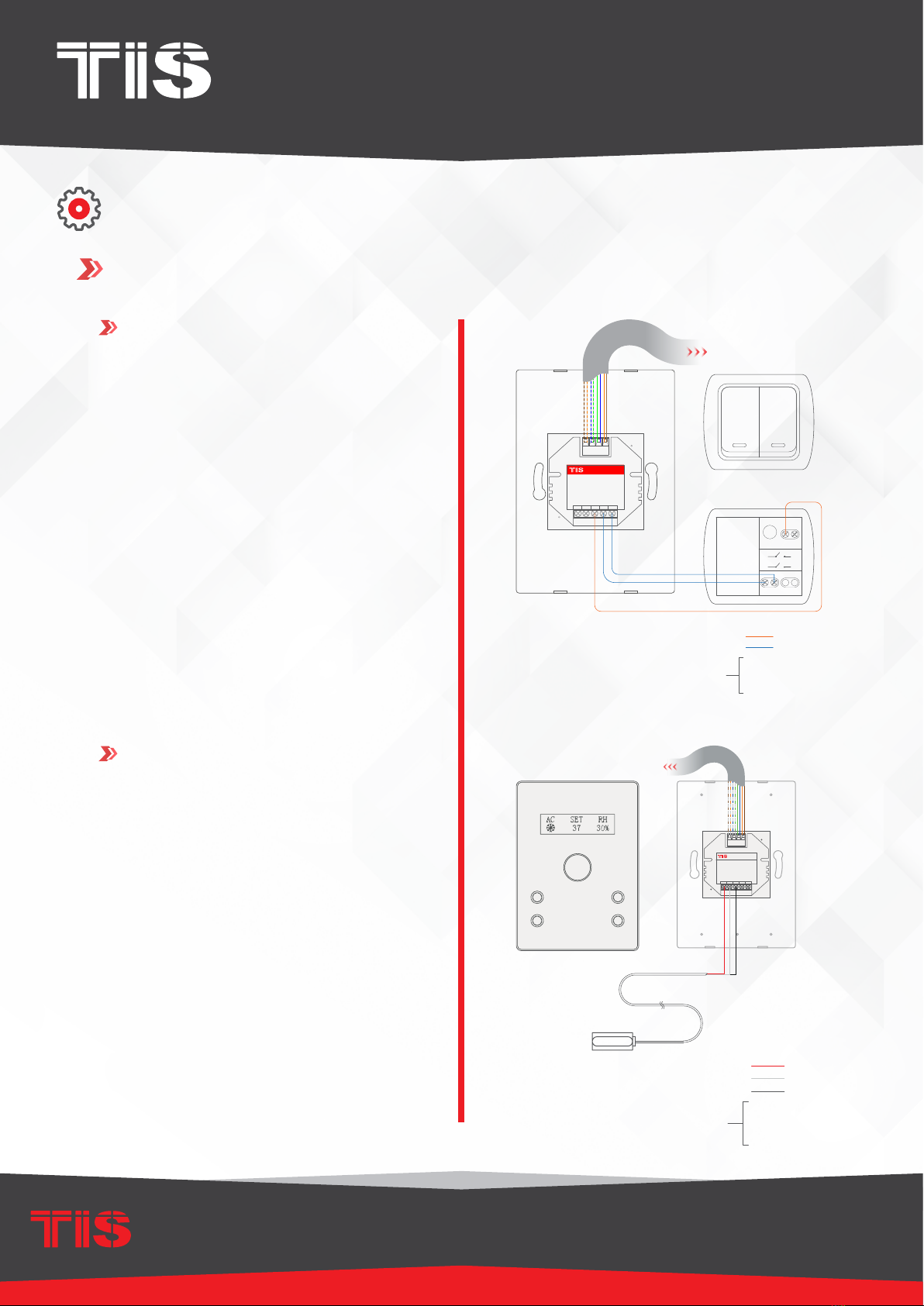
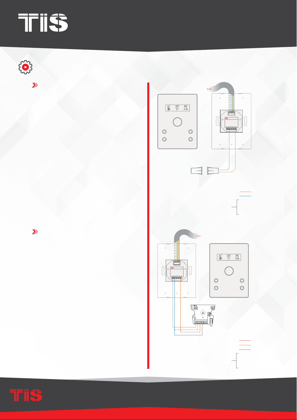
7Connect the other connection if needed as per the panel addition type.
FOR PANEL ADDITION 2DL-IRR
You can connect 2 digital inputs to any
switch or window magnet.
You can add an External Infrared Receiv-
er to the IRR Port, connect as follows:
▸
the IR Receiver black wire to GND
▸
Gray wire to REC
▸
Red wire to VCC Terminal.
PANEL ADDITION
2 Digital Input with IR Receiver
Model : ADD-2DL-IRR
TIS BUS Input : 45mA/24V DC
VCC REC GND Z2 Z1
www.tissmarthome.com
D- +24V
GND D+
To the TIS BUS Network
Cat5e
GND(white-orange)&(white-brown)
D-(white-green)&(white-blue)
D+(blue-green)
+24V(brown-orange)
Cat5econnection
low voltage cable
low voltage cable
Traditional Switch
L
S2
S1
S1
L
L
S2

INSTALLATION MANUAL
MODEL: IO-AC-4G
TIS CONTROL LIMITED
RM 1502-p9 Easey CommBldg
253-261 Hennessy Rd Wanchai
Hong Kong
TEXAS INTELLIGENT SYSTEM LLC
SUITE# 610. 860 NORTH DOROTHY DR
RICHARDSON
TX 75081.USA
Copyright © 2020 TIS, All Rights Reserved
TIS Logo is a Registered Trademark of Texas Intelligent System LLC in the
United States of America. This company takes TIS Control Ltd. in other
countries. All of the Specifications are subject to change without notice.
www.tiscontrol.com
THERMOSTAT WITH 4 PUSH-BUTTON PANEL
7
GND(white-orange)&(white-brown)
D-(white-green)&(white-blue)
Cat5e connection
+24V(brown-orange)
D+(blue-green)
low voltage cable
low voltage cable
PANEL ADDITION
2 Digital Input with IR Emitter
Model : ADD-2DL-IRE
TIS BUS Input : 45mA/24V DC
IR- IR+ GND Z2 Z1
www.tissmarthome.com
D- +24V
GND D+
TIS IR Emitter probe
To the TIS BUS Network
Cat5e
IO-AC-4G
GND(white-orange)&(white-brown)
D-(white-green)&(white-blue)
D+(blue-green)
+24V(brown-orange)
Cat5e connection
low voltage cable
low voltage cable
PANEL ADDITION
2 Digital Input with IR Receiver
Model : ADD-2DL-IRR
TIS BUS Input : 45mA/24V DC
VCC REC GND Z2 Z1
www.tissmarthome.com
D- +24V
GND D+
Door Magnet Contact
To the TIS BUS Network
Cat5e
IO-AC-4G
INSTALLATION STEPS
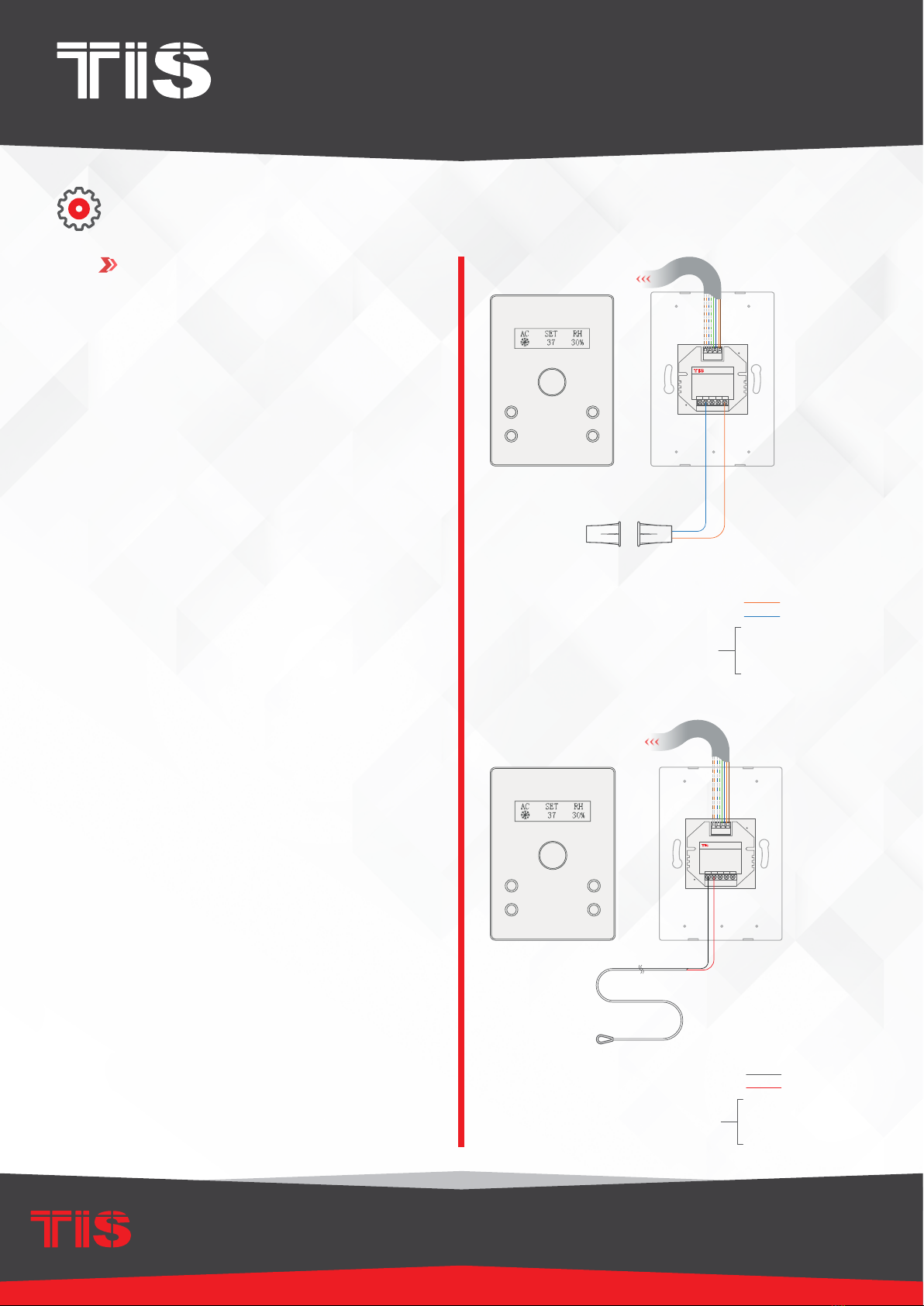
FOR PANEL ADDITION 2DL-IRE
You can connect 2 digital inputs to any
switch or window magnet.
▸
Connect the IR Emitter Probe’s positive
wire to IR+ terminal.
▸
Connect the negative wire to IR-terminal.

INSTALLATION MANUAL
MODEL: IO-AC-4G
TIS CONTROL LIMITED
RM 1502-p9 Easey CommBldg
253-261 Hennessy Rd Wanchai
Hong Kong
TEXAS INTELLIGENT SYSTEM LLC
SUITE# 610. 860 NORTH DOROTHY DR
RICHARDSON
TX 75081.USA
Copyright © 2020 TIS, All Rights Reserved
TIS Logo is a Registered Trademark of Texas Intelligent System LLC in the
United States of America. This company takes TIS Control Ltd. in other
countries. All of the Specifications are subject to change without notice.
www.tiscontrol.com
THERMOSTAT WITH 4 PUSH-BUTTON PANEL
8
GND(white-orange)&(white-brown)
D-(white-green)&(white-blue)
D+(blue-green)
+24V(brown-orange)
Cat5e connection
low voltage cable
low voltage cable
low voltage cable
3rd party sensor
PANEL ADDITION
3 Digital Input with 12V Output
Model : ADD-3DL-12V
TIS BUS Input : 45mA/24V DC
+12V GND Z3 Z2 Z1
www.tissmarthome.com
Output: DC 12V/50mA
D- +24V
GND D+
C5
C2
PULSE
1&2
2&3
NONE
1P
2P
3P
RELAY
1&2
2&3
NO
NC
1 2 3
RELAY
1&2
2&3
NO
NC
1 2 3
TAMPERALARM12V GND
CON1
1 2 3
LED1
818-6B V2.3
2016-11-09
To the TIS BUS Network
Cat5e
IO-AC-4G
GND(white-orange)&(white-brown)
D-(white-green)&(white-blue)
D+(blue-green)
+24V(brown-orange)
Cat5e connection
low voltage cable
low voltage cable
PANEL ADDITION
3 Digital Input with 12V Output
Model : ADD-3DL-12V
TIS BUS Input : 45mA/24V DC
+12V GND Z3 Z2 Z1
www.tissmarthome.com
Output: DC 12V/50mA
D- +24V
GND D+
Door Magnet Contact
To the TIS BUS Network
Cat5e
IO-AC-4G
INSTALLATION STEPS
FOR PANEL ADDITION 3DL-12V
You can connect 3 digital inputs to any
switch or window magnet.
Also, you can connect any 12V operated
smoke detector or any 3rd party sensor
with NC/NO connection to the 12V GND
and Z1-Z3 terminals as per the diagram.

INSTALLATION MANUAL
MODEL: IO-AC-4G
TIS CONTROL LIMITED
RM 1502-p9 Easey CommBldg
253-261 Hennessy Rd Wanchai
Hong Kong
TEXAS INTELLIGENT SYSTEM LLC
SUITE# 610. 860 NORTH DOROTHY DR
RICHARDSON
TX 75081.USA
Copyright © 2020 TIS, All Rights Reserved
TIS Logo is a Registered Trademark of Texas Intelligent System LLC in the
United States of America. This company takes TIS Control Ltd. in other
countries. All of the Specifications are subject to change without notice.
www.tiscontrol.com
THERMOSTAT WITH 4 PUSH-BUTTON PANEL
9
GND(white-orange)&(white-brown)
D-(white-green)&(white-blue)
D+(blue-green)
24+V(brown-orange)
Cat5e connection
1.5 mm Electric Cable
2.5
mm Electric Cable
Open
Close
220 ~ 110 Volt
Connect To N
Connect To L
O-OFF
I-ON
MCB
PANEL ADDITION
3 Output Relay 5 Amp
Model : ADD-3R-5A
TIS BUS Input : 45-75mA/24V DC
Output Current : 3A220VAC
COM OUT3 OUT2 OUT1 COM
www.tissmarthome.com
D- +24V
GND D+
to the TIS BUS Network
Cat5e
IO-AC-4G
GND(white-orange)&(white-brown)
D-(white-green)&(white-blue)
D+(blue-green)
+24V(brown-orange)
Cat5e connection
1.5 mm Electric Cable
2.5 mm Electric Cable
PANEL ADDITION
3 Output Relay 5 Amp
Model : ADD-3R-5A
TIS BUS Input : 45-75mA/24V DC
Output Current : 3A220VAC
COM OUT3 OUT2 OUT1 COM
www.tissmarthome.com
D- +24V
GND D+
Connect To L
O-OFF
I-ON
MCB
Connect To N
IO-AC-4G
To the TIS BUS Network
Cat5e
INSTALLATION STEPS
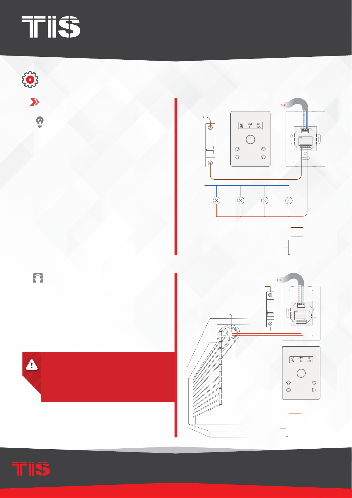
LIGHTING CONNECTION
▸
Connect the live wire to COM
▸
Connect the loads wire to Out1-Out3
to terminals
▸
Connect load neutral wire to main
neutral in the distributor box.
SHUTTER / CURTAIN CONNECTION
▸
Connect the Supply wire to COM
▸
Connect the Open wire to OUT1
▸
Connect the Close wire to OUT2
▸
Shutter neutral connection, if it exists,
can be looped to main neutral in the
distributor box.
FOR PANEL ADDITION 3R-5A
WARNING: Set the curtain function in the
software before connecting the wires.

INSTALLATION MANUAL
MODEL: IO-AC-4G
TIS CONTROL LIMITED
RM 1502-p9 Easey CommBldg
253-261 Hennessy Rd Wanchai
Hong Kong
TEXAS INTELLIGENT SYSTEM LLC
SUITE# 610. 860 NORTH DOROTHY DR
RICHARDSON
TX 75081.USA
Copyright © 2020 TIS, All Rights Reserved
TIS Logo is a Registered Trademark of Texas Intelligent System LLC in the
United States of America. This company takes TIS Control Ltd. in other
countries. All of the Specifications are subject to change without notice.
www.tiscontrol.com
THERMOSTAT WITH 4 PUSH-BUTTON PANEL
10
1.5 mm Electric Cable
2.5 mm Electric Cable
GND(white-orange)&(white-brown)
D-(white-green)&(white-blue)
D+(blue-green)
+24V(brown-orange)
Cat5e connection
COOL
HEAT
FAN
COM
PANELADDITION
3 Output Relay 5 Amp
Model : ADD-3R-5A
TIS BUS Input : 45-75mA/24V DC
Output Current : 3A220VAC
COM OUT3 OUT2 OUT1 COM
www.tissmarthome.com
D- +24V
GND D+
To the TIS BUS Network
Cat5e
GND(white-orange)&(white-brown)
D-(white-green)&(white-blue)
D+(blue-green)
24+V(brown-orange)
Cat5e connection
1.5 mm Electric Cable
2.5
mm Electric Cable
PANELADDITION
3Output Relay 5 Amp
Model: ADD3-R5-A
TISBUS Input : 75-45mA/24V DC
OutputCurrent : 3A220VAC
COM OUT3 OUT2 OUT1 COM
www.tissmarthome.com
D- 24+V
GND D+
Connect To L
O-OFF
I-ON
MCB
LOW
MEDIUM
HIGH
To the TIS BUS Network
Cat5e
IO-AC-4G
INSTALLATION STEPS
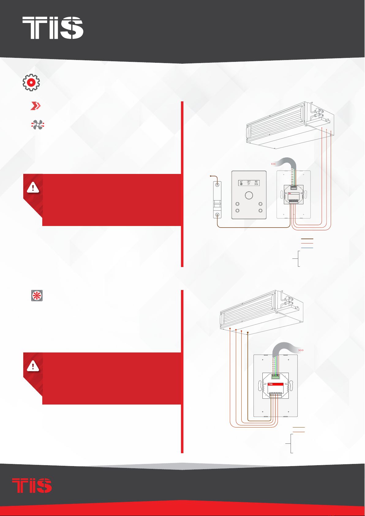
FCU CONNECTION
▸
Connect the supply wire to com
▸
Connect the FAN Low, Medium, and
High wires to Out1, Out2, and Out3 in
the same order.
HVAC CONNECTION
▸
Connect the HVAC COM (supply)
wire to COM
▸
Connect the Cool, Heat, and FAN
wires to Out1, Out2, and Out3 in the
same order.
FOR PANEL ADDITION 3R-5A
WARNING: Set the FCU function in the
software before connecting the wires.
WARNING: Set the HVAC function in the
software before connecting the wires.
Tabla de contenidos
Otros manuales de Termostato de TIS
Manuales populares de Termostato de otras marcas

EWELLY
EWELLY EW-181 Manual de usuario

Prolon
Prolon T1100 Instrucciones de instalación

Computherm
Computherm Q20 Manual de usuario

Heatmiser
Heatmiser neoStat Manual de usuario

Aube Technologies
Aube Technologies TH111GFCI-NP 240 VCA Manual de usuario

Mars
Mars HEAT CONTROLLER IR Wireless Thermostat Manual de usuario