Thytronic DTB 49-50 Manual de usuario

DTB
1
DTB000\08
4-95
DTB
Relè di protezione termica
Thermal protection relay
MANUALED'ISTRUZIONE
INSTRUCTIONMANUAL
49-50

DTB000\08
4-95
2
0 - INDICE
1 - DESCRIZIONE
2 - CARATTER
ISTICHE
DI FUNZIONA-
MENTO
3 - PRINCIPIO DI FUNZIONAMENTO
4 - INSTALLAZIONE
5 - TARATURA
6 - MESSA IN SERVIZIO
7 - PROCEDURE DI PROVA
0 - CONTENTS
1 - DESCRIPTION
2 - FUNCTION CHARACTERISTICS
3 - FUNCTION PRINCIPLE
4 - INSTALLATION
5 - SETTING
6 - COMMISSIONING
7 - TESTING PROCEDURES
3
4
12
14
19
24
26

DTB
3
DTB000\08
4-95
DESCRIZIONE
Generalità
Il relè di protezione termica tipo DTB, come tutti
i tipi della serie DENOVA SYSTEM, è costituito da
un modulo estraibile e da una controbase. Que-
st'ultima assolve la funzione di interconnessione e
di supporto meccanico, mentre tutti i circuiti di
misura e di elaborazione sono alloggiati nel modu-
lo estraibile. Il relè è disponibile nelle diverse
configurazioni meccaniche adatte per montaggio:
- incassato,
- sporgente, con morsetti anteriori,
- a rack.
Le caratteristiche costruttive principali sono:
- custodia in materiale isolante, completamente
protetta contro la penetrazione di corpi estranei
e polvere;
- connettore con contatti argentati a 6 punti di
contatto e distanze d'isolamento largamente
dimensionate;
- regolazioni frontali mediante microinterruttori,
rese inaccessibili mediante copertura traspa-
rente sigillabile;
- circuiti di alimentazione ausiliaria stabilizzati e
dotati di accumulo di energia contro le interru-
zioni della tensione ausiliaria;
- ingressi di misura isolati galvanicamente e larga-
mente dimensionati contro i sovraccarichi per-
manenti e transitori;
- circuiti autodiagnostici di controllo interno.
Pannello frontale
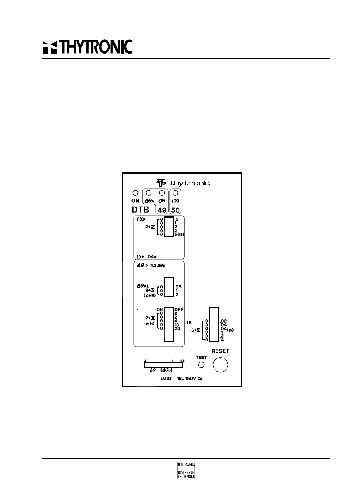
Il pannello frontale è suddiviso in due zone
corrispondenti alle due funzioni di protezione espli-
cate dal relè DTB e comprende:
- dispositivo di taratura a microinterruttore per la
soglia e il tempo d'intervento,
- indicatore luminoso a LED.
Una zona non colorata, riguardante entrambe
le funzioni di protezione, comprende:
- dispositivo di taratura a microinterruttori della
corrente di base I
B
,
- pulsante di prova TEST,
- pulsante di ripristino RESET,
- indicatore ON a LED della condizione di relè
funzionante.
Sul pannello frontale sono rappresentati i se-
guenti dati di targa:
- marchio di fabbrica,
- tipo del relè,
- campo d'impiego della tensione ausiliaria,
- corrente nominale,
- frequenza nominale.
DESCRIPTION
General
The thermal protection relay type DTB, as well
as all the other types of the line DENOVA SYSTEM,
is composed by a withdrawable unit and a
counterbase unit. The last one performs the function
of electrical connection and mechanical frame,
while all the measuring circuits are housed in the
extractible module. The relay is available with the
different mechanical configurations, suitable for
the following mountings:
- flush,
- projecting, with front connections,
- rack.
The principal characteristics are:
- case made of insulating material, completely
protected against the penetration of extraneous
objects and dust;
- connector with 6-contact silver plated recepta-
cles and overdimensioned insulation distances;
- front plate dip-switches, available for all the
necessary adjustments, protected by means of
a transparent cover;
- self stabilized auxiliary supply circuit, provided
with an energy storage circuit to result insensitive
to the interruptions of the auxiliary voltage;
- input measuring circuits with galvanic isolation
and overdimensioned components, to tolerate
disturbances and transient, as well as
permanent, overloads;
- internal self-test circuits.
Front plate
The front plate is subdivided in two areas
referring to a single protection function performed
by relay DTB and contains:
- microswitch adjusting device for threshold setting
and operation time,
- LED operation indicator.
A not coloured area refers, at the same time, to
both protection functions and comprises:
- microswitch adjusting device for for the base
current I
B
,
- TEST pushbutton,
- RESET pushbutton,
- LED indicator, marked ON, meaning the relay to
work.
On the front plate the following information is
indicated:
- manufacturer name,
- type of relay,
- operative range for the auxiliary voltage,
- nominal current,
- nominal frequency.

DTB000\08
4-95
4
CARATTERISTICHE DI FUNZIONA-
MENTO
Simbologia
Le grandezze caratteristiche riguardanti il fun-
zionamento del relè DTB e i relativi simboli rappre-
sentativi sono elencate di seguito.
I
N
Corrente nominale d'entrata del relè,
coincidente con la corrente nominale secon-
daria dei TA.
I
B
Corrente di base: rappresenta la cor-
rente nominale della macchina protetta,
espressa in rapporto alla corrente nominale
dei TA.
I
P
Corrente assorbita dalla macchina pri-
ma della condizione di sovraccarico, in rife-
rimento alle curve d'intervento a caldo della
funzione termica.
∆Θ
B
Sovratemperatura di base: rappresen-
ta la sovratemperatura della macchina in
corrispondenza all'assorbimento della sua
corrente nominale I
B
.
∆Θ> Soglia d'intervento della protezione termica,
espressa in rapporto alla sovratemperatura
di base ∆Θ
B
.
∆Θ
AL
Soglia d'allarme termico, espressa in rap-
porto alla sovratemperatura di base ∆Θ
B
.
τCostante di riscaldamento: rappresen-
ta la costante di tempo del modello termico.
I>> Soglia d'intervento di massima
corrente per la protezione di corto circuito,
espressa in rapporto alla corrente di base I
B
.
FUNCTION CHARACTERISTICS
Symbols
The characteristic quantities concerning the
function of relay DTB and the corresponding
symbols are explained below.
I
N
Relay input nominal current, coincident
with the secondary nominal current of the
CT's.
I
B
Base current: it represents the nominal
current of the protected machine, referred to
the the nominal current of the CT's.
I
P
Current drawn by the machine before
the overload condition, with reference to the
hot operation curves of the thermal function.
∆Θ
B
Base overtemperature: it represents
the overtemperature of the machine, corre-
sponding to the drain of its nominal current
I
B
.
∆Θ> Operation threshold for the thermal
protection, expressed with reference to the
base overtemperature ∆Θ
B
.
∆Θ
AL
Thermal alarm threshold, expressed with
reference to the base overtemperature ∆Θ
B
.
τHeating time constant: it represents
the time constant of the thermal model.
I>> Overcurrent operation threshold for
the short circuit protection, expressed with
reference to the base current I
B
.
FUNZIONE SOGLIA D'INTERVENTO TEMPO D'INTERVENTO
FUNCTION OPERATION THRESHOLD OPERATION TIME
COD. RIF. CAMPO DI REGOL. RISOL. CAMPO DI REGOL. RISOL.
CODE REF. SETTING RANGE RESOL. SETTING RANGE RESOL.
-IB0.5...1.3 IN0.02 IN--
49 ∆ΘAL 0.8...1.15 ∆ΘB0.05 ∆ΘB--
49 ∆ΘB1.2 ∆ΘB---
49 τ-- - 2...40 min 2 min
50 I>> 2...12.5 IB0.5IB0.04 s -
Regolazioni
I valori di taratura delle soglie e dei tempi
d'intervento sono riportati nelle seguente tabella.
Adjustments
The setting values of thresholds and operation
times are indicated in the following table.

DTB
5
DTB000\08
4-95
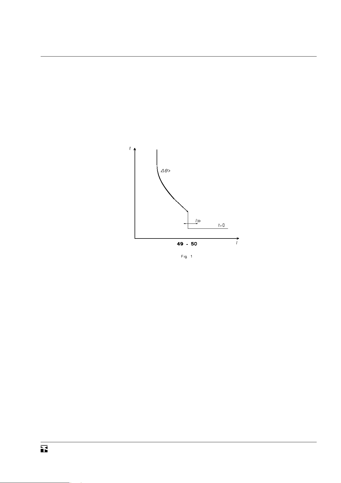
General operation characteristics
The general operation characteristics of the
relay DTB are shown qualitatively in the diagram of
fig. 1. It shows the operation of the following
protection functions:
49 thermal protection,
50 overcurrent protection.
Caratteristiche generali d'intervento
Le caratteristiche d'intervento del relè DTB sono
rappresentate in modo qualitativo nel diagramma
di fig. 1. Esso rappresenta l'intervento delle se-
guenti funzioni di protezione:
49 protezione termica,
50 protezione di massima corrente.

DTB000\08
4-95
6
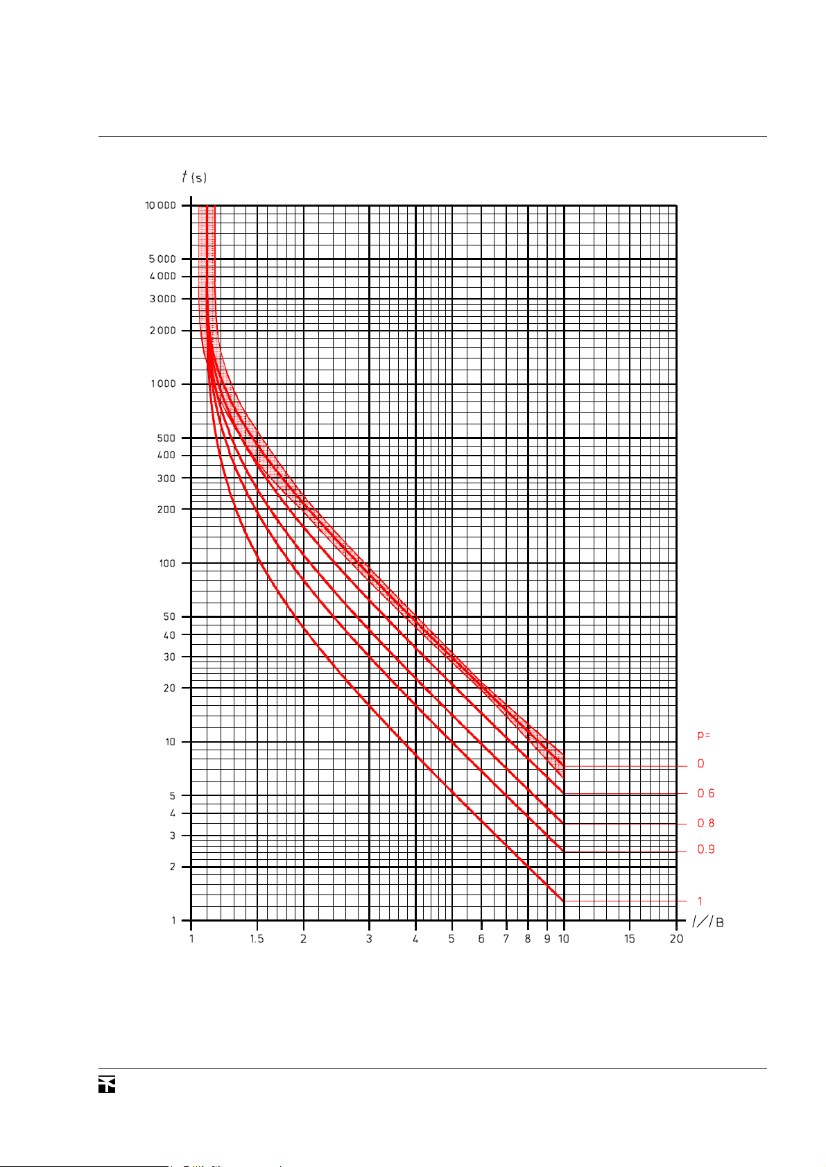
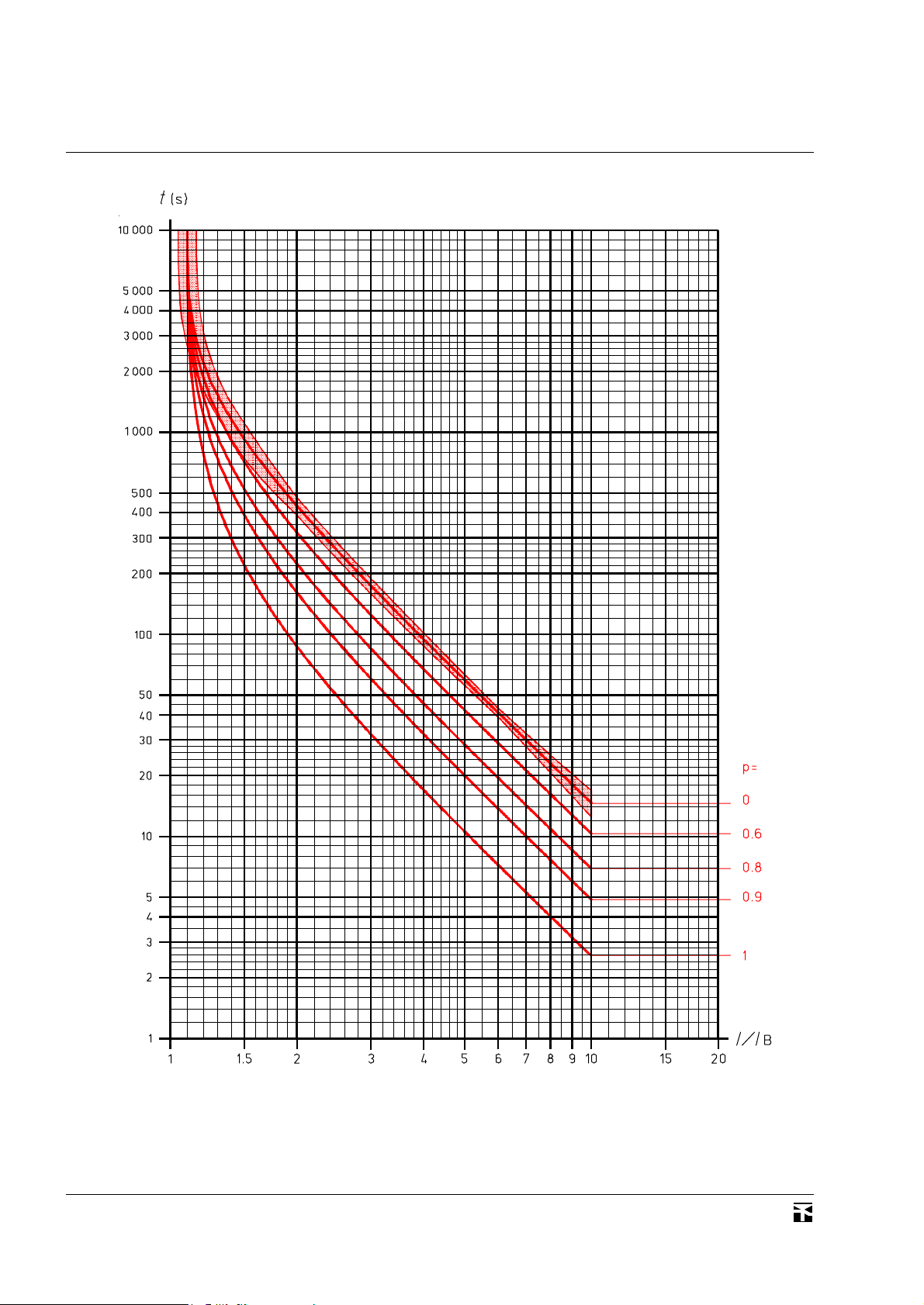
Caratteristiche d'intervento della funzione
termica
La funzione termica riproduce l'effetto riscal-
dante delle correnti che percorrono gli avvolgimenti
della macchina protetta e pertanto è una funzione
a tempo dipendente.
Le caratteristiche d'intervento riportate nelle
fig. 2...6 si basano sulle seguenti condizioni di
riferimento:
- applicazione istantanea di un determinato valore
costante di corrente,
- corrente perfettamente equilibrata.
I diversi diagrammi riportati corrispondono ad
alcuni valori di taratura della costante termica di
riscaldamento τ. Comunque, poichè i tempi d'inter-
vento riportati in ordinata sono proporzionali al
valore della costante termica τ, i tempi d'intervento
corrispondenti ad altro valore di τsi ottengono
moltiplicandoli in proporzione.
I valori indicati in ascisse sono costituiti dal
rapporto I / I
B
tra la corrente a cui si desidera
determinare il tempo d'intervento e il valore di
taratura della corrente di base I
B
. Naturalmente
entrambe le correnti devono essere riferite al
primario del TA, oppure entrambe al secondario.
Le diverse curve riportate in ogni diagramma
sono identificate dai diversi valori del coefficiente
di precarico p, in quanto la funzione termica è del
tipo a memoria totale. Pertanto se la macchina si
trova nella condizione di regime corrispondente
ad una corrente di valore
I
P
= p ·I
B
al momento in cui la corrente assume il valore di
sovraccarico, il relativo tempo d'intervento è de-
terminato dalla curva identificata da tale valore di
p.Come detto sopra, le curve d'intervento si rife-
riscono a condizioni di funzionamento ipotetiche
(corrente di valore costante per tutto il tempo di
sovraccarico, perfettamente equilibrata).
Tuttavia la funzione termica, per sua natura,
tiene realmente conto del riscaldamento della
macchina anche in occasione di correnti variabili
nel tempo e non equilibrate.
Operation characteristics of the thermal
function
The thermal function reproduces the heating of
the protected machine caused by the currents
flowing in the windings, then it is a dependent time
function.
The operation characteristics presented in the
fig. 2...6 are based upon the following reference
assumptions:
- instantaneous application of a constant prede-
termined current value,
- exactly balanced current.
The different diagrams, represented in the fol-
lowing, correspond to a number of setting values
of the heating time constant τ. However, as the
operation times indicated in the ordinates are
proportional to the value of the thermal constant τ,
the times corresponding to other values of τcan be
computed by a proportional factor.
The values indicated on abscissa are expressed
as the ratio I / I
B
between the current for wich it is
required to determine the operation time and the
setting value of the base current I
B
. Obviously both
currents must be referred to the primary of the
CT's, or both to the secondary.

The different curves drawn on every diagram
are identifyable by a different value of the preload
factor p, as the thermal function is a total memory
type. Therefore if the machine is working in a

steady state condition corresponding to a current
equal to
I
P
= p ·I
B
before the current changes to an overload value,
the relevant operation time is determined by the
curve identified by such a value of coefficient p.
As above mentioned, the operation curves refer
to a theoretical working condition (constant value
of the current along all the overload time duration,
perfectly balanced current).
However the thermal function really takes into
account for the heating effect on the machine as
well of time variable currents as of unbalanced
currents.

DTB
7
DTB000\08
4-95
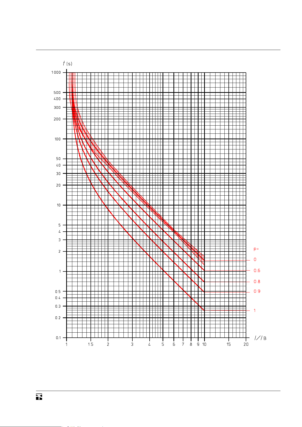
Caratteristiche d'intervento della funzione ter-
mica, corrispondenti a diversi stati termici prece-
denti; valore della costante termica τpari a 2 min.
Operation characteristics of the thermal function,
corresponding to different previous thermal condi-
tions; value of the thermal constant τequal to 2
min.

DTB000\08
4-95
8
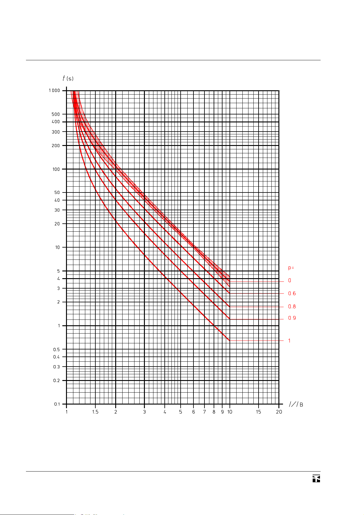
Caratteristiche d'intervento della funzione ter-
mica, corrispondenti a diversi stati termici prece-
denti; valore della costante termica τpari a 5 min.
Operation characteristics of the thermal function,
corresponding to different previous thermal condi-
tions; value of the thermal constant τequal to 5
min.

DTB
9
DTB000\08
4-95
Caratteristiche d'intervento della funzione ter-
mica, corrispondenti a diversi stati termici prece-
denti; valore della costante termica τpari a 10 min.
Operation characteristics of the thermal function,
corresponding to different previous thermal condi-
tions; value of the thermal constant τequal to 10
min.

DTB000\08
4-95
10
Caratteristiche d'intervento della funzione ter-
mica, corrispondenti a diversi stati termici prece-
denti; valore della costante termica τpari a 20 min.
Operation characteristics of the thermal function,
corresponding to different previous thermal condi-
tions; value of the thermal constant τequal to 20
min.
Tabla de contenidos
Otros manuales de Relé de Thytronic

Thytronic
Thytronic NV021 Manual de usuario

Thytronic
Thytronic NV10B Manual de usuario

Thytronic
Thytronic RMT/3 Guía

Thytronic
Thytronic NV10P Manual de usuario

Thytronic
Thytronic NA20 Manual de usuario

Thytronic
Thytronic DMC3S Manual de usuario

Thytronic
Thytronic RMT/8D Guía

Thytronic
Thytronic NA11 Manual de usuario

Thytronic
Thytronic Pro-N NVA100X-D Manual de usuario

Thytronic
Thytronic SIF5600 Manual de usuario