Thermo Sphere 12V SE Manual de usuario

INSTRUCTION GUIDE
HEATING | WALL
TOWEL BARS
Live well....
ThermoSphere 12V SE Towel
Bar Installation Guide

2+44 (0) 800 019 5899
Warranty terms &
conditions
ThermoSphere covers all its products
with a satisfaction guarantee. In
addition, ThermoSphere will supply a
replacement product where a fault is
shown to be caused by manufacture,
materials or workmanship providing the
goods have been installed correctly and
according to installation instructions.
This guarantee does not include removal,
freight or installation costs.
To use the warranty, repair or service
the customer must provide purchase
invoice/receipt, and completed warranty
registration form.
If the product develops a fault within
the warranty period due to normal wear
and tear, ThermoSphere at its discretion
will recognise whether it‘s a faulty
product or not. If it is impossible or not
economical for the manufacturer to
repair the product, the manufacturer will
replace the faulty product with a new
unit of the same model or if there is no
stock available of the same model as the
product, the manufacturer will replace
the product with a new unit of a similar
size. No responsibility can be taken for
altered dimensions and lining up of
existing holes.
The repair service offered within the
warranty period only covers the faults
and problems as developed from the
manufacturer‘s errors. Any damage
caused by improper use or carelessness
or incorrect wiring is not covered.
ThermoSphere is not responsible for
any monetary loss or injuries caused
by improper use or installation of this
product.
Please Note: Full Terms and Conditions
are available on request.
request your copy or give us a call.
Safety and care
information
ThermoSphere Towel Bars should be
connected to the electrical supply by a
qualied electrician and in accordance
with current local regulations.
We recommend that the towel bar is
installed with the bottom bar at least
600mm from the oor and with a
300mm clearance from permanent
xtures.
Recommended spacing between bars
is 150mm
ThermoSphere Heated Towel Bars can
be xed onto timber stud, steel stud or
masonry (solid or cavity) walls.
Stud walls require noggins at the correct
position for all xings and if the exact
position cannot be determined early in
the job, we recommend using noggins
covered with 18mm construction ply or
OSB covering a larger area.
Fixing to plasterboard or cement
sheeting alone is not recommended and
will not hold long term.
ThermoSphere SE Towel Bars are
designed to be installed BEFORE TILING
and as such it is imperative that the
xing spigot and/or mounting system is
installed perfectly level. We recommend
using a laser level and checking the level
periodically throughout installation.
Towel bars are 12V SELV (safety extra
low voltage) and can be installed in
bathrooms.
Ensure any controls used are installed in
correct zone according to the IP rating
of the control
Ensure that your towel bar is protected
by a suitably rated RCD
Do not use the towel bar to hold
towels or other articles that have been
in contact with oil, petroleum based
products or dry cleaning uids
This appliance is intended to warm and
dry towels not heat spaces
Do not immerse your towel bar in liquid
Ensure the transformer is located no
further than 2m from the ThermoSphere
Towel Bar
Ensure the transformer is accessible and
has adequate ventilation
Care information
The Stainless Steel nish of your
towel bar is hard wearing and easy to
maintain. However any harsh scrubbing,
scratching or acid based cleaning
products will damage the surface of
your towel rail.
Clean with a soft cloth dampened with
warm and warm soapy water only. Dry
immediately for the best nish.
Max weight warning
ThermoSphere SE Towel bars are
designed to hold towels only, and must
not be subjected to excessive forces over
10kg and must not be climbed on or
used as support rails.
This can result in injury and can cause
damage to the towel bars which is not
covered under the guarantee.

Contents
What's in the box? .........................................
Key considerations .........................................
Single bar installation .....................................
Multiple bar installation ..................................
Example wall build up .....................................
Wiring schematics ..........................................
Available models .............................................
4
5
6
9
13
14
15
Watch the installation videos!
Single SE Bar installation
without mounting system
Multiple SE Bar installation
with mounting system
4+44 (0) 800 019 5899
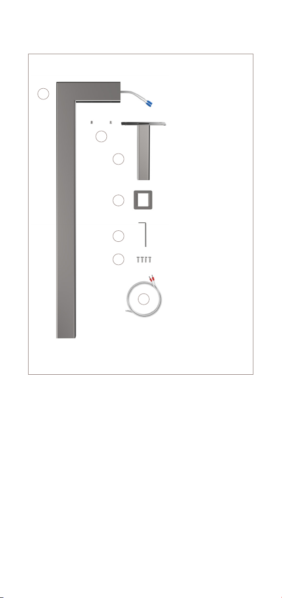
What’s in the box?
You will also need
1. Towel bar body
2. Grub screws
3. Mounting spigot
4. Dress ring
5. Hex key
6. Mounting screws
7. Power lead 2m
• Fixings that are suitable for your wall substrate
• Laser level or spirit level
• Cordless drill or impact driver
• Marker pen or pencil
• 30mm diamond hole cutter bit
• 25mm timber hole cutter bit
• Suitable rated 12V transformer
• 230V electrical supply
• Fibreglass mesh tape
1
2
3
4
5
6
7

Key considerations
Fixing spigots must be installed before tiling!
You MUST make sure xing spigots are level!
Low voltage transformers
Max tiling depth is 35mm
Use the right xings for your wall substrate
SE Towel Bars xing spigots are designed for installation before
tiling. You must install the xings spigots and run cables before
you tile the wall. There is no option to install SE Towel Bars on
top of a tiled wall.
Because the xing spigots are installed behind the tiles, you
have to take extra care to make sure they are installed level. We
recommend using a laser level throughout the process to check
the towel bars are nice and level!
SE Towel Bars are 12V DC and there is no polarity. You must
install a suitably rated 12V transformer between the towel bar
and the 230V supply. You can connect multiple towel bars to
one transformer in parallel, up to the maximum load of the
transformer. The transformer should be somewhere accessible to
facilitate replacement.
The maximum depth of the tiled wall layers that will be situated
over the xing spigot is 35mm. This includes any boards, tile
adhesive and the tiles. Limiting the tiling depth ensures that
there is enough spigot protruding from the wall to achieve a
good, strong xing to the towel bar.
We recommend that you x SE Towel Bars to a solid wall, such
as a brick/block cavity wall, a secure timber noggin within a
cavity wall or a plywood/OSB panel. Use xings that are suitable
for the type of wall you are xing to. We do not recommend
xing directly to plasterboard or tile backer boards as this can
cause the xings to move over time and result in loose towel
bars.
MAX 35MM
Fixing
spigot
plate
Tiling layers Towel bar
chassis
Grub screws
Spigot shaft inside
bar chassis

6+44 (0) 800 019 5899
Installing single bars
(No mounting system)
Loosen the grub screws with
a hex key.
Drill a hole in the noggin
big enough to pass the
connection cables through
(22-25mm).
Remove the spigot and dress
ring and keep safe to one side.
Feed the connection cables
through the hole and up to a
12V transformer.
Ensure the spigot is level and
mark xing holes. A laser level
is recommended.
Pull the connection cables
through the spigot and a
screw in the top right corner.
1
3
5
2
4
6
Level check!
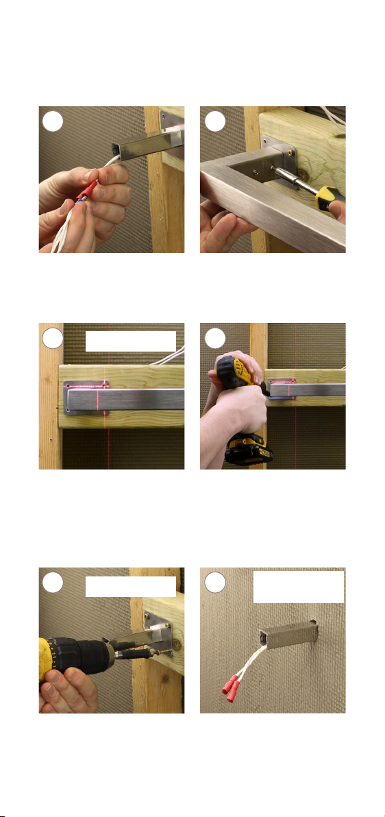
Plug in the red and blue bullet
connectors and push excess
cable through the noggin.
Reinstate the towel bar and
tighten the grub screws with
a hex key.
Adjust the level of the towel
bar using a laser level and
hold in position.
Fix a screw into the bottom
left hole of the mounting plate
and check the level again.
Only when you‘re happy with
the level, t the remaining
xing screws.
Cut a 22mm hole in the wall
board that is going over the
spigot. Secure with screws
and washers.
7
9
11
8
10
12
Level check!
Level check! Max tiling
depth 35mm

8+44 (0) 800 019 5899
Cut a 30mm hole in the
tile that is situated over the
mounting spigot and tile the
wall as normal.
Fit the towel bar, locate the
dress ring and tighten the
grub screws.
And you’re done!
Once tile adhesive has dried,
place the dress ring over the
spigot and t the towel bar.
Plug in the red and blue bullet
connectors (12V no polarity)
and feed excess cable into the
wall cavity.
13
15
14
16
Max tiling
depth 35mm

Installing multiple bars
(With a mounting system)
Loosen the grub screws with
the hex key.
Feed a connection cable
through each spigot leaving at
lead 80mm of cable to work
with
Remove the spigot and dress
ring and keep safe to one side.
Fix a screw into the top right
corner and pull cables up to
the 12V transformer before
xing the mounting system in
position.
Pass each spigot through the
back of the mounting system
and x tightly with 4x10mm
xing screws.
Plug in the red and blue
bullet connectors and feed
any excess cable behind the
mounting system.
1
3
5
2
4
6
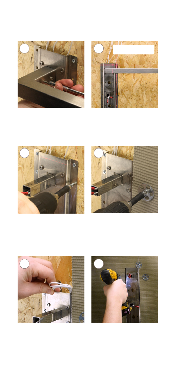
10 +44 (0) 800 019 5899
Position the towel bar over the
spigot taking care not to pinch
the cables. Tighten the grub
screws with a hex key.
Make sure the towel bars are
level before proceeding. Only
when you are happy with the
level, secure the bottom left
xing screw
Now remove the towel bar,
unplug the connection cables
and secure the mounting
system to the wall with
suitable screws.
Level check!
Fix tile backer/insulation
boards to the wall ush with
the front of the mounting
system. Follow the board
manufacturer guidelines.
Drill a hole and feed the
connection cables through
the wall cavity to a 12V
transformer. Do not drill the
cables!
Cut a tile backer board to t
around the mounting system
and x with screws and
washers. Make the wall ready
for tiling.
7
9
11
8
10
12
Tabla de contenidos
Otros manuales de Accesorio de baño de Thermo Sphere


