
TFA Dostmann KlimaLogg Pro Manual de usuario

KlimaLogg Pro
Kat.No. 30.3039.IT
Temperature and Humidity Logger
INSTRUCTION MANUAL
100*140mm

INSTRUCTION MANUAL
KlimaLogg Pro
Cat. No. 30.3039.IT
Temperature and Humidity Logger
INTRODUCTION:
Thank you for choosing this this professional temperature and humidity
data logger from TFA.
BEFORE YOU USE IT
Please be sure to read the instruction manual carefully.
This information will help you to familiarise yourself with your new device,
learn all of its functions and parts, find out important details about its first
use and how to operate it, and get advice in the event of faults.
Following the instruction manual for use will prevent damage to the
device and loss of your statutory rights arising from defects due to
incorrect use. We shall not be liable for any damage occurring as a result
of not following these instructions. As well we shall not be liable for any
incorrect readings and any consequences that occur should an
inaccurate reading take place.
Please take particular note of the safety advice!
Please look after this manual for future reference.
FIELD OF OPERATION
This device allows you to make detailed recordings of the temperature
and humidity and to actively monitor them. Recorded data can be
transferred to a computer using a USB transceiver for easy analysis. The
supplied software can also be used for managing the logger and can be
used purely as windows service to provide datasets to your own software
application. The logger is able to use up to eight outdoor transmitters.
For your safety:
The product is exclusively intended for the field of application
described above. The product should only be used as described
within these instructions.
Unauthorised repairs, modifications or changes to the product are
prohibited.

Caution!
Risk of injury:
Keep this instrument and the batteries out of reach of children.
Batteries must not be thrown into the fire, short-circuited, taken
apart or recharged. Risk of explosion!
Batteries contain harmful acids. Low batteries should be changed
as soon as possible to prevent damage caused by a leaking
battery. Never use a combination of old and new batteries together
or batteries of different types. Wear chemical-resistant protective
gloves and glasses when handling leaked batteries.
! Important information on product safety!
Extreme temperatures, vibration and shock should be avoided as
these may cause damage to the units and give inaccurate
readings.
Protect from moisture.Do not submerge the units in water
Avoid placing the instrument near interference sources/metal
frames such as computer or TV sets.

CONTENTS:
Chapter:
Features
Additional transmitters
Installation and replacement of the batteries
First installation
DCF radio controlled time reception
LCD display
Buttons
Function of the buttons
Basic settings
Transmitters
Learning-Mode
Recording interval setting
Max.Min.-values and current dew point
Alarm-setting mode
Alarmevent-data set-function
History mode
PC-connection
Open-collector hardware output
Troubleshooting
Positioning of the logger
Care and maintenance
Battery replacement
Waste disposal
Specifications

LCD display
Buttons
Battery
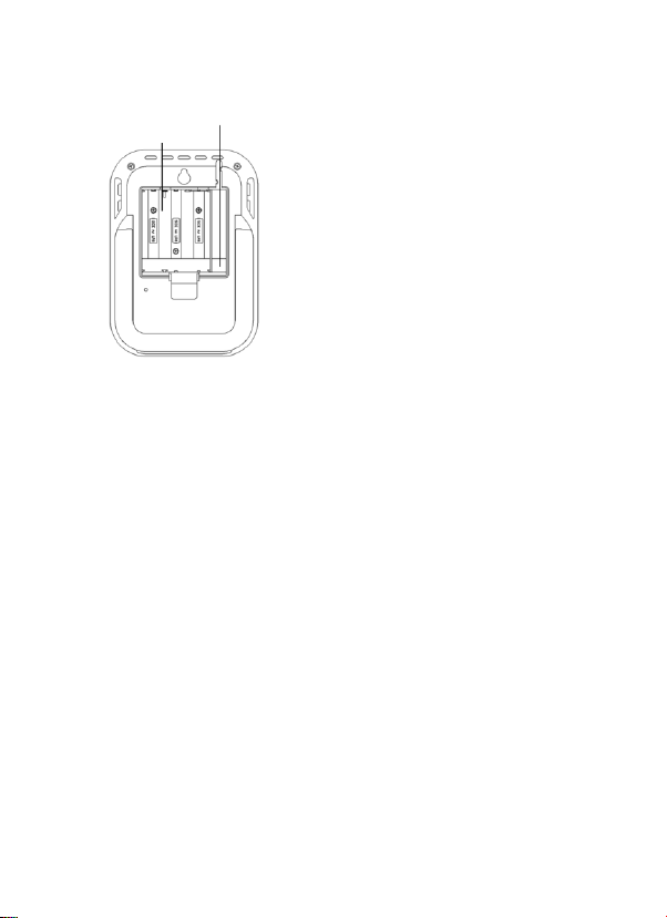
compartment
Stand (fold out)
Hanging hole
FEATURES:
Indication of the current temperature and humidity
DCF radio controlled time and date
MIN/MAX values and time of reception
Indication of the current dew point
Temperature display in ºC/ ºF
12 or 24 hour time mode
Time zone option ±12 hours
LCD contrast selectable
Low battery indicator
Data logging function –up to 50000 data records
Logging intervals 1, 5, 10, 15, 30 minutes or 1, 2, 3, 6 hours
Data sets can be called up either directly on the device or using a
PC
Display of the data sets that have not yet been read out in %
Up to 8 transmitters receivable (temperature and humidity
transmitter or only temperature transmitter with external cable
sensor)
Text display with predefined serial number or individual name
assignment for transmitters that have been received
Manual learning function for all transmitters or individual
transmitters
Status display upon loss of transmitter signals
Data transfer via USB wireless transceiver

Individual alarm limits for all channels can be set with visual and /
or acoustic alarm
Additional generat of “AlarmEvent” data sets when an alarm is
triggered
Switching output for alarm output to external hardware
Table standing or wall mounting
Including easy-to-use Windows software
ADDITIONAL TRANSMITTER (purchased separately)
You have the possibility to receive up to eight additional external
transmitters with your KlimaLogg Pro. These are separately available in
specialist shops.
INSTALLATION AND REPLACEMENT OF THE BATTERIES:
Note:
If you have purchased external transmitters, you should insert the
batteries into the transmitters just before into the KlimaLogg Pro. For
more information, please have a look at the chapter “transmitters” of this
manual or refer the instruction manual of the transmitter.
The instrument operates with three 1,5 V batteries Type Mignon AA.
For installation and replacement of the batteries, please follow the steps
below:
Temperature & Humidity
Kat. No.: 30.3180.IT
Temperature with external cable
Kat. No.: 30.3181.IT
1. Insert finger or other solid object
in the space at the bottom
center of the battery
compartment and lift up to
remove the cover.
2. Insert the batteries, pay
attention to their correct polarity.
3. Insert compartment cover and
close it.
FIRST INSTALLATION:
When the KlimaLogg Pro is powered up, a short beep will sound and all
LCD segments will light up.
The KlimaLogg Pro shows the current temperature and humidity values.
“INDOOR” is displayed in the text field, and 00:00:00 and 01.01.10 are
displayed in the time and date area (the device counts up the time until
the DCF signal has been received or the time and date are manually
set).
After the KlimaLogg Pro has been started up, it searches for external
transmitters for three minutes. After a battery change, the transmitters
that were entered previously are once again assigned the channel that
had previously been assigned to them. External transmitters that had not
been previously detected are automatically entered on a available
channel.
DCF RADIO CONTROLLED TIME RECEPTION
After the KlimaLogg Pro has searched for external transmitters for
three minutes, the device begins to search for the DCF signal
(german radio-controlled clock signal), and the DCF reception
indicator flashes. If the time code has been received after 5-10
minutes, the radio-controlled time is displayed and the DCF
reception indicator remains on the LCD.
Battery
compartment
Connector socket
Open Collector

In case the clock cannot detect the DCF-signal (for example due to
disturbances, transmitting distance, etc.), the time can be set
manually.
The clock will then work as a normal quartz clock. (see: Basic
settings/Time and calendar).
The radio controlled clock receives the signals at 2:00 and 3:00
o'clock in the morning.
As soon as the clock has received the DCF signal, the manually
set time will be overwritten by the DCF time.
Note that during reception of the radio-controlled clock signal, no
communication with the USB wireless transceiver is possible or
may be briefly interrupted.
Note for Radio Controlled Time DCF:
The base for the radio controlled time is a Caesium Atomic Clock
operated by the Physikalisch Technische Bundesanstalt Braunschweig
which has a time deviation of less than one second in one million years.
The time is coded and transmitted from Mainflingen near Frankfurt via
frequency signal DCF-77 (77.5 kHz) and has a transmitting range of
approximately 1500 km. Your Logger receives this signal and converts it
to show the precise time in summer or wintertime. The quality of the
reception depends greatly on the geographic location. In normal cases,
there should be no reception problems within a 1,500 km radius around
Frankfurt.
Recommended distance to any interfering sources like computer
monitors or TV sets is a minimum of 1.5 - 2 metres.
Within ferro-concrete rooms (basements, superstructures), the received
signal is naturally weakened. In extreme cases, please place the unit
close to a window and/or point its front or back towards the Frankfurt
transmitter.
During night-time, the atmospheric disturbances are usually less severe
and reception is possible in most cases. A single daily reception is
adequate to keep the accuracy deviation below 1 second.

LCD DISPLAY:
The LCD display is split into 7 sections.
The designation of each section can be found on the following figure:
BUTTONS:
The logger is equipped with 7 function buttons:
Channel Display
Indication of the transmitters that
were entered, status
information, current selected channel
Text Display
Indication of the channel’s name
(or serial number) or guidelines
Indication Humidity
Indication Temperature
Memory Indication
Indication of the logging interval
and display of the data sets that
have not yet been read out in %
Indication of time and date
Toolbar
DCF symbol, Alarm sound,
Alarm ON/OFF, USB, History (HIST)
and Learning Mode (LRN)-Symbol

FUNCTIONS OF THE BUTTONS IN THE NORMAL VIEW:
History / Delete go to the history-mode of the recorded data sets
USB (single press)
initiate the contact with the known USB
transceiver
(press and hold for three seconds)
Synchronization to an USB transceiver
SET (single press)
go to the setting mode of the transmitter (Learn
mode).
With a further press you go to the record interval
setting.
(press and hold for three seconds)
go to the basic setting mode of the logger
Alarm (single press)
deactivate active alarm sound if an alarm is
happend
(press and hold for three seconds)
go to the alarm setting mode of the currently
displayed channel.
OK / Max.Min. call up the Max.Min. values and the current dew
point of the selected channel
Plus Scroll up through the available channels
Minus Scroll down through the available channels
BASIC SETTINGS:
In normal mode, press and hold the SET button for 3 seconds to enter
the manual setting mode for the following functions:
- LCD contrast
- Time zone
- Alarm sound ON/OFF
Tabla de contenidos


