MRC DW-6092 Manual de usuario

SD card real time data logger
3 PHASE
POWER ANALYZE
R
Model : DW-6092
Y
our purchase o
f
this 3 PHASE
POWER ANALYZER
marks a step
forward for you into
the field o
f
precision
measurement.
A
lthough this
POWER ANALYZER
is a complex and
delicate instrument,
its durable structure
will allow many
years of use i
f
proper operating
techniques are
developed. Please
read the following
instructions
carefully and always
keep this manual
within easy reach.
OPERATION MANUAL

Caution Symbol
Caution :
* Risk of electric shock !
* During the measurement,
do not open the cabinet.
Caution :
* Do not apply the overload
voltage, current to the input
terminal !
* Remove test leads before open
the battery cover !
* Cleaning - Only use the dry
cloth to clean the plastic case !
Environment Conditions
* Installation Categories III 600V.
* Pollution Degree 2.
* Altitude up to 2000 meters.
* Indoor use.
* Relative humidity 80% max.

TABLE OF CONTENTS
1. FEATURES...............................................................
.
1
2. SPECIFICATIONS.....................................................
.
2
2-1 General Specifications........................................
.
2
2-2 Electrical Specifications.......................................4
3. FRONT PANEL DESCRIPTION....................................
.
8
4. MEASURING PREPARATION ......................................10
4-1 The original screen.............................................
.
10
4-2 Entry the measurement Screen............................ 10
4-3 The summary description of keyboard.................. 12
4-4 SETUP KEY description........................................ 13
4-5 Setting function description before measuring....... 14
5. MEASURING PROCEDURES .......................................35
5-1 1Φ2W ( one phase by two wires )
measurement..................................................... 35
5-2 1Φ3W ( one phase by three wires )
measurement..................................................... 36
5-3 3Φ3W ( three phase by three wires )
measurement..................................................... 38
5-4 3Φ4W ( three phase by four wires )
measurement..................................................... 39
5-5 The CT and PT measurement...............................41
5-6 Data Logger function..........................................
.
43
5-7 Data Hold function............................................ 45
5-8 Backlight key...................................................... 46
5-9 A ( Current ) Range key......................................
.
46
5-10 LOWBAT screen................................................ 48
5-11 Appendix 1....................................................... 49
6. MAINTENANCE......................................................... 50
6-1 Cleaning.............................................................50
6-2 Replacement of batteries ....................................50
7. RS232 PC SERIAL INTERFACE...................................
.
51
8. Download the saving data from the SD card to
the computer ( EXCEL software ) .............................. 53
9. PATENT...................................................................
.
57
10. THE E ADDRESS OF AFTER SERVICE CENTER ..........58

1. FEATURES
* Analysis for 3 phase multi-power system, 1P/2W,
1P/3W, 3P/3W, 3P/4W
*Voltage & Current are the True RMS value.
* True Power ( KW、MW、GW ) measurement.
* Apparent Power ( KVA、MVA、GVA ) measurement.
* Reactive Power ( KVAR MVAR、GVAR) measurement.
* Watt-Hour ( WH、SH、QH、PFH ).
* Power Factor( PF )、Phase Angle( Φ).
* Voltage measurement range : 10 to 600 ACV
* Current measurement range: 0.2A to 1200 ACA.
* Programmable CT ratio (1 to 600) and PT ratio (1 to 1000).
* ACV input impedance is 10 Mega ohms.
* Safety Standard : IEC 1010, CAT III 600V
*Built-in clock and Calendar, real time data record with
SD memory card , sampling time set from 2 to 7200
seconds. Just slot in the SD card into the computer, it
can down load the all the measured value with the
time information ( year/month/data/
hour/mimute/second ) to the Excel directly, then user
can make the further data analysis by themselves.
* Complete set with 4 PCs Test Leads, 4 PCs Alligator
clips, 3 PCs Clamp Probe, AC to DC 9V adapter,
2 G SD memory card and Carrying bag.
* Computer data output, can cooperate with USB Cable
/USB-01 RS232 cable/UPCB-02 and Data Acquisition
software, SW-U801-WIN.
1

2. SPECIFICATIONS
2-1 General Specifications:
Circuit Custom one-chip of microprocessor LSI
circuit
Display * LCD Size :
81.4 X 61 mm ( 3.2 X 2.4 inch )
* Dot Matrix LCD (320 X 240 pixels )
with back light.
Measurement * ACV
* ACA
* AC WATT ( True Power )
AC WATT( Apparent Power )
AC WATT( Reactive Power )
* Power factor
* Phase angle
* Frequency
Wire 1P/2W, 1P/3W, 3P/3W, 3P/4W.
connections
Voltage ranges 10 ACV to 600 ACV, auto range.
Current ranges 0.2 ACA to 1200 ACA,
auto range/manual range.
Safety IEC1010 CAT III 600 V.
standard
ACV input 10 Mega ohms.
impedance
Range select ACV Auto range.
ACA Auto range & manual range.
Clamp 40 Hz to 1 KHz.
frequency
response
Spec. tested 45 to 65 Hz.
frequency
Over load ACV 720 ACV rms
protection ACA 1300 ACA with clamp probe
CP-1200
2

Over Indicator Show " OL ".
Under Indicator Show " UR ".
Data Hold Freeze the display reading.
Data Record SD Card Record.
Sampling Time Approx. 1 second.
Power ON/OFF Manual OFF by push button.
Real time * Real time data logger, saved the data
data logger into SD memory card and down load
the all the measured value with the
time information ( year/month/data/
hour/mimute/second ) down load
to the Excel
* Integration time for data logger :
2 seconds to 7200 seconds, the during
of setting step are 2 seconds.
Data Output RS232 computer serial interface :
USB/RS232 * Connect the optional USB cable
* Computer
USB-01 will get the USB plug.
interface
* Connect the optional RS232 cable
UPCB-02 will get the RS232
plug.
Operating 0 to 50 ( 0 to 122 ).℃℉
Temperature
Operating Less than 80% R.H..
Humidity
Power Supply * DC 1.5V, AA ( UM-3 ) Battery X 8 PCs
(Alkaline or heavy duty battery).
* AC to DC 9V power adapter.
Power * Meter : 300 DCmA.
Consumption * Clamp : 20 DCmA.
Clamp max. 86 mm ( 3.4 inch ) Dia.
conductor
Size
3

Weight * Meter: 1049g ( includes batteries )
* Clamp : 522g
Dimension
Meter :
225 X 125 X 64 mm
( 8.86 X 4.92 X 2.52 inch )
Clamp :
210 X 64 X 33mm
( 8.3 X 2.5 X 1.3 inch )
Clamp Jaw : 86 mm (3.4 inch)- outside
Accessories * Instruction manual.............. 1 PC
Included *
T
est Leads (TL88-4AT)........ 1 Set (4 PCs)
* Alligator clips (TL88-4AC) 1 Set (4 PCs)
* Clamp Probe ( CP-1200 )..... 3 PCs
*
A
C to DC 9V adapter...........
.
1 PC
* SD card ( 2 G )...................
.
1 PC
* Carryin
g
ba
g
.......................1 PC
Optional * USB Cable , USB-01
Accessories * RS232 cable, UPCB-02
* Data Acquisition software,
SW-U801-WIN
2-2 Electrical Specifications:
ACV
Range Resolution Accuracy
10.0V to 600.0V 0.1V ± (0.5%+0.5V)
* Phase to neutral line
10.0V to 600.0V
* Phase to phase
4
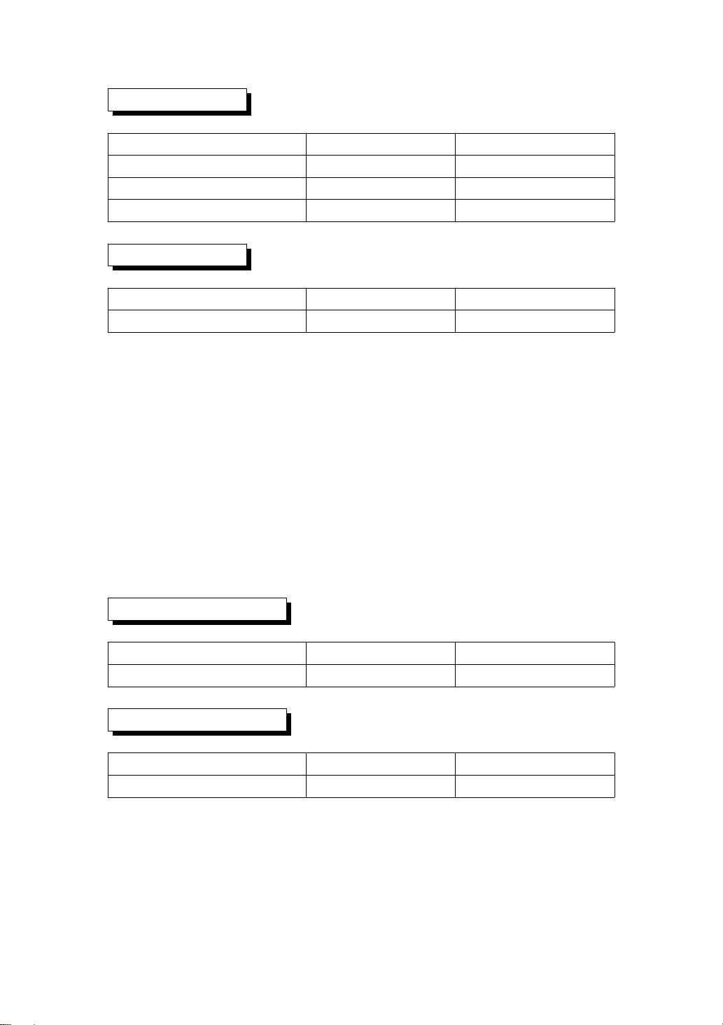
ACA
Range Resolution Accuracy
20A 0.001A/0.01A ± (0.5%+0.1A)
200A 0.01A/0.1A ± (0.5%+0.5A)
1200A 0.1A/1A ± (0.5%+5A)
Power factor
Range Resolution Accuracy
0.00 to 1.00 0.01 ± 0.04
Remark :
* PFH : Long term power factor
* PFΣ:
For 3Φ4W, 3Φ3W
PFΣ= ( PF1 + PF2 + PF3 )/3
For 1Φ3W
PFΣ= ( PF1 + PF2 )/2
Φ( Phase angle )
Range Resolution Accuracy
-180° to 180° 0.1° ± 1°
* ACOS ( PF )
Frequency
Range Resolution Accuracy
45 to 65 Hz 0.1 Hz 0.1 Hz
5
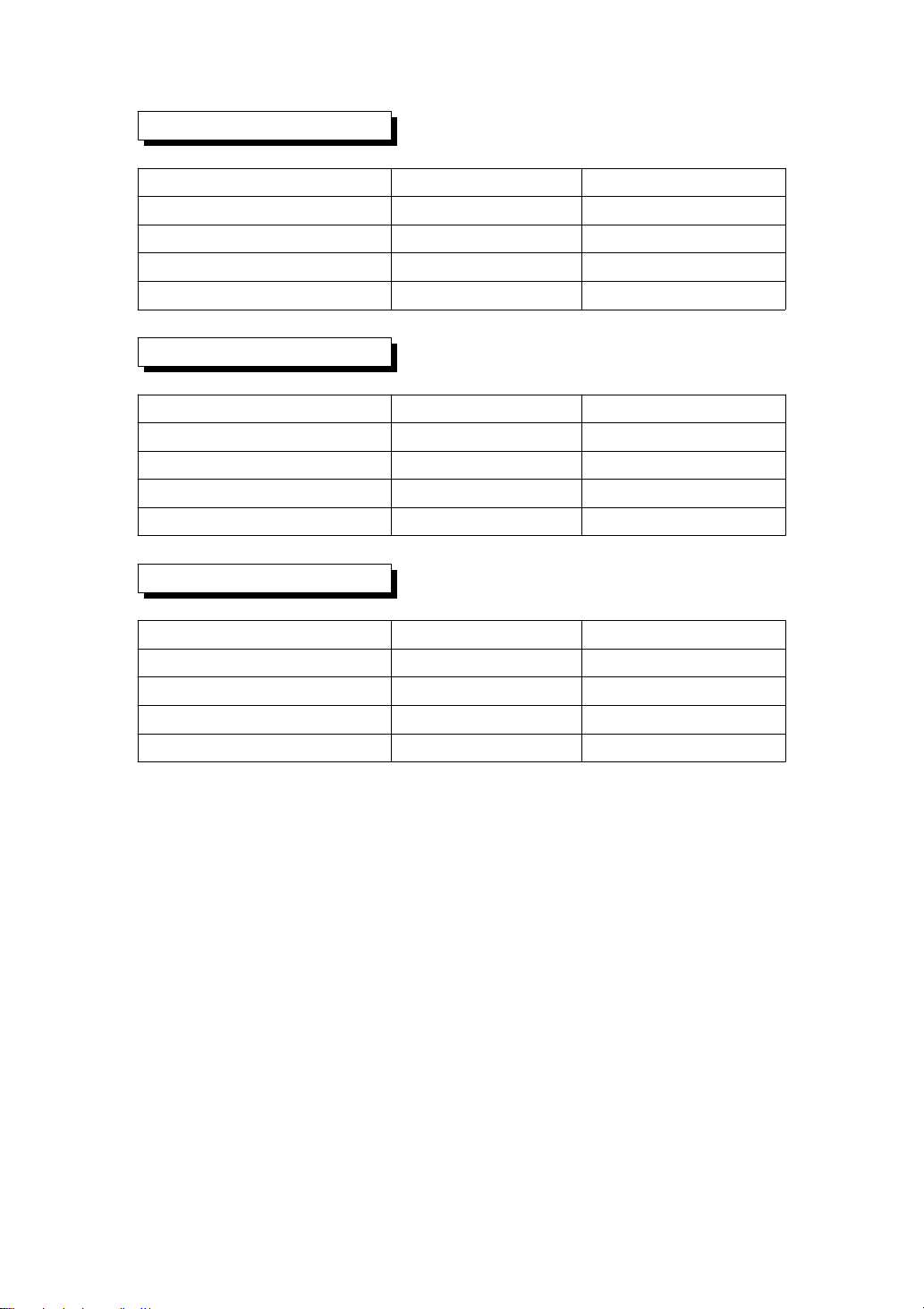
Active (Real) Power
Range Resolution Accuracy
0.000 to 9.999 KW 0.001 KW ± (1%+0.008KW)
10.00 to 99.99 KW 0.01 KW ± (1%+0.08KW)
100.0 to 999.9 KW 0.1 KW ± (1%+0.8KW)
0.000 to 9.999 MW 0.001 MW ± (1%+0.008MW)
Apparent Power
Range Resolution Accuracy
0.000 to 9.999 KVA 0.001 KVA ± (1%+0.008KVA)
10.00 to 99.99 KVA 0.01 KVA ± (1%+0.08KVA)
100.0 to 999.9 KVA 0.1 KVA ± (1%+0.8KVA)
0.000 to 9.999 MVA 0.001 MVA ± (1%+0.008MVA)
Reactive Power
Range Resolution Accuracy
0.000 to 9.999 KVAR 0.001 KVAR ± (1%+0.008 KVAR)
10.00 to 99.99 KVAR 0.01 KVAR ± (1%+0.08 KVAR)
100.0 to 999.9 KVAR 0.1 KVAR ±(1%+0.8KVAR)
0.000 to 9.999 MVAR 0.001 MVAR ± (1%+0.008 MVAR)
6

Watt Hour ( Active Power Hour) : WH
Range Resolution Accuracy
0.000 to 9.999 KWH 0.001 KWH ± (2%+0.008 KWH)
10.00 to 99.99 KWH 0.01 KWH ± (2%+0.08 KWH)
100.0 to 999.9 KWH 0.1 KWH ±(2%+0.8KWH)
0.000 to 9.999 MWHR 0.001 MWH ± (2%+0.008 MWH)
VA Hour ( Apparent Power Hour ) : SH
Range Resolution Accuracy
0.000 to 9.999 KVAH 0.001 KVAH ± (2%+0.008 KVAH)
10.00 to 99.99 KVAH 0.01 KVAH ± (2%+0.08 KVAH)
100.0 to 999.9 KVAH 0.1 KVAH ±(2%+0.8KVAH)
0.000 to 9.999 MVAH 0.001 MVAH ± (2%+0.008 MVAH)
VAR Hour ( Reactive Power Hour ) : QH
Range Resolution Accuracy
0.000 to 9.999 KVARH 0.001 KVARH ± (2%+0.008 KVARH)
10.00 to 99.99 KVARH 0.01 KVARH ± (2%+0.08 KVARH)
100.0 to 999.9 KVARH 0.1 KVARH ± (2%+0.8 KVARH)
0.000 to 9.999 MVARH 0.001 MVARH ± (2%+0.008 MVARH)
7
Tabla de contenidos
Otros manuales de Registrador de datos de MRC


