Tenda K4P-4TR Manual de usuario

Installation Guide
PoE HD Video Security Kit

CONTENTS
English
Dansk
Suomi
Eesti
Latviešu
Svenska
Slovenčina
Nederlands
Lietuvių
Hrvatski
Magyar
Slovenščina
Українська
Български
Deutsch
Italiano
Français
Español
Indonesian
Türkçe
Русский
Polski
Čeština
Português
Română
01
10
19
28
37
46
55
64
73
82
91
100
109
118
127
136
145
154
163
172
181
190
199
208
217
226
235
•••••••••••••••••••••••••••••••••••••••••••••••••••••••••••••••••••••
•••••••••••••••••••••••••••••••••••••••••••••••••••••••••••••••••••••••
••••••••••••••••••••••••••••••••••••••••••••••••••••••••••••
•••••••••••••••
•••••••••••••••••••••••••••••••••••••••••••••••••••••••••••••••••
••••••••••••
••••••••••••••••••••••••••••••••••••••••••••••••••••••••••••••••
••••••••
•••••••••••••••••••••••••••••••••••••••••••••••••••••••••••••••••••••••••
••••••••••••••••••••••••••••••••••••••••••••••••••••••••••••••••••••••
•••••••••••••••••••••••••••••••••••••••••••••••••••••••••••••••••••••
••••••••••••••••••••••••••••••••••••••••••••••••••••••••••••••••••••••••••
••••••••••••••••••••••••••••••••••••••••••••••••••••••••••••••••••••••••
•••••••••••••••••••••••••••••••••••••••••••••••••••••••••••••••••••••••••
•••••••••••••••••••••••••••••••••••••••••••••••••••••••••••••••••••••••••
•••••••••••••••••••••••••••••••••••••••••••••••••••••••••••••••••••
•••••••••••••••••••••••••••••••••••••••••••••••••••••••••••••••••
•••••••••••••••••••••••••••••••••••••••••••••••••••••••••••••••••••
•••••••••••••••••••••••••••••••••••••••••••••••••••••••••••••••••••••••
•••••••••••••••••••••••••••••••••••••••••••••••••••••••••••••••••••••••••
•••••••••••••••••••••••••••••••••••••••••••••••••••••••••••••••••••••••
••••••••••••••••••••••••••••••••••••••••••••••••••••••••••••••••••••••••
••••••••••••••••••••••••••••••••••••••••••••••••••••••••••••••••••••
•••••••••••••••••••••••••••••••••••••••••••••••••••••••••••••••••••••••••
••••••••••••••••••••••••••••••••••••••••••••••••••••••••••••••••••••••
••••••••••••••••••••••••••••••••••••••••••••••••••••••••••••••••••••
••••••••••••••••••••••••••••••••••••••••••••••••••••••••••••••••••
••••••••••••••••••••••••••••••••••••••••••••••••••••••••••••••
••••••••••••••••••••••••••••••••••••••••••••••••••••••••••••••••
••••••••••••••••••••••••••••••••••••••••••••••••••••••••••••••••••

POWER
Է И
Л
Й
К М
PoE HD Video Security Kit
Quick Installation Guide

Ԯ
ԯ
Ա
Բ
Գ
Դ
Ե
- 1 -
Wall mounting hole
English
Package contents
Զ
Է
И
Й
К
Л
М
Network Video Recorder x 1 Screwdriver×1
HDMI cable×1
1m Ethernet cable×1
18m Ethernet cable×2
30m Ethernet cable×2
Surveillance sticker×1
Quick installation guide
PoE Camera×4
Power adapter x 1
NVR installation package x 1
Camera installation package x 4
Mouse x 1
Waterproof kit×4
HDD×1
Only equipped in some kits
Screw: Thread diameter: 3.5 mm; Length: 5 mm; Head diameter: 6.5 mm
− Machine screw: Thread diameter: 6 mm; Length: 6 mm
− Self-tapping screw: Thread diameter: 6 mm; Length: 25 mm
− Plastic anchor: External diameter: 6.0mm; Length: 25mm
POWER LED indicator
Hard disk drive
(HDD) screw hole
Power port
AUDIO OUT port USB2.0 port
HDMI port
10/100 Mbps PoE power supply and
data transmission multiplexing port
Grounding terminal
10/100 Mbps LAN port
AUDIO IN port
VGA port
POWERPOWER PoE PORTS LAN AUDIO HDMI
OUT
1 3
2 4
VGA USB1 USB2
IN
Solid blue: Initializing.
Solid green: NVR recording.
NVR (The N6P-4H is taken as an example here.)
Blinking green: NVR working properly but not recording.
Solid red: NVR faulty (LAN port disconnected, or HDD faulty).
The K4P-4TR Kit is taken as an example here. The actual product prevails.
Appearance
Camera
Screw hole for pendant mounting Screw hole for wall mounting
Microphone
Ethernet port, 10/100 Mbps auto-negotiation
The camera supports the IEEE 802.3af standard, this port can be
connected to the PoE port of a PoE power sourcing equipment
for power supply.

-2-
Grounding terminal.
Connect the grounding terminal of the NVR to the earth or the ground terminal of the building
with a grounding cable to prevent static electricity or lightning from damaging the NVR.
Power port.
Use the included power adapter to power on the NVR.
POWER
PoE
PORTS
LAN
AUDIO
IN
AUDIO
OUT
HDMI
VGA
USB
Fast Ethernet LAN port.
Used to connect to such devices as the router and switch.
Audio input port.
Used to connect to the audio input devices , such as pickups.
Audio output port.
Used to connect to audio output devices, such as active speakers.
HDMI port.
Connect your monitor or TV to this port using an HDMI cable for audio and video output.
VGA port.
Connect your monitor to this port using a VGA cable for video output.
USB 2.0 port.
Used to connect to such devices as a mouse and a USB storage device.
DescriptionPort
Tips
- Recommended Ethernet cable: CAT 5 or better.
- Power supply distance:
• Normal Mode (default): Up to 100m
• Long-range Mode: Up to 250m
Fast Ethernet port, which supports IEEE 802.3af/at PoE power supply. Used to connect to
cameras.
Tips
When installing or replacing the HDD, please cut off the power supply of the NVR, otherwise the HDD may not be
detected or even be damaged.
I Install the HDD
If the kit does not include any HDD, please prepare it by yourself. You are recommended to use the HDD
dedicated for surveillance.
ԮUse a screwdriver to unfasten the screws, then remove the cover of the NVR. Reserve the screws for
later use.
POWER
POWER PoE PORTS LAN AUDIO HDMI
OUT
1 3
2 4
VGA USB1 USB2
IN
Flip
Remove the cover
Wall-mounting holes
Wall-mounting materials are self-prepared. Recommended specifications of the plastic
screws and anchors:
Screw: thread diameter: 3 mm, length: 14 mm; head diameter: 5.2 mm
Plastic anchor: inner diameter: 6.0 mm; length: 26.4 mm

- 3 -
ԯTake out 2 screws from the NVR installation package, and screw them into the two screw holes
closest to the SATA connector. Reserve about 2 mm between the screws head and the HDD for
subsequent installation.
Align the SATA connector of the HDD with the SATA slot on the motherboard of the NVR, and then
insert the HDD into the slot until it is tightly fixed.
ԱTake out the remaining screws from the NVR installation package, and screw them into the HDD
screw holes to fix the HDD.
ԲMount the cover with the previously removed screws.
SATA connector
HDD
HDD
HDD
POWER
POWER PoE PORTS LAN AUDIO HDMI
OUT
1 3
2 4
VGA USB1 USB2
IN

- 4 -
II Install the camera
Tips
Please make sure the wall or the ceiling is strong enough to withstand three times the weight of the camera.
You may need to prepare a hammer drill, a drill bit, a rubber hammer, a screwdriver, and a ladder for the installation.
−
−
Fix the camera
Install the waterproof kit
The camera supports wall and pendant mounting. The mounting bracket of wall mounting is included in
the package. If you want to install the camera by pendant mounting, please purchase the bracket by
yourself.
The wall mounting is taken as an example here.
You can install the waterproof kit and wrap the end with waterproof tape for the Ethernet port as required.
When you connect the Ethernet cable to the Ethernet port of the camera, the waterproof kit installation
steps are as follows.
Բ Գ
Marker pen
Horizontal adjustment screw
Swing bracket
Vertically adjust
Horizontally adjust
Vertical adjustment screw
Ԯ ԯ
Ա
Unfasten the horizontal adjustment screw on the
bottom, rotate the swing bracket to a suitable angle,
and then fasten the screw.
Install the camera (Running the cable through the wall
is taken as an example) Adjust the monitoring direction and fix the camera
Thread diameter: 6 mm; Length: 6
mm machine screw
Anchor
Thread diameter: 6 mm;
Length: 25 mm
self-tapping screw
Horizontal adjustment screw
The included waterproof kit is not suitable for the Ethernet cable with protection cover on the
crystal head. See the example on the right.
Tips
Ԯ ԯ
Բ
Ա
- 5 -
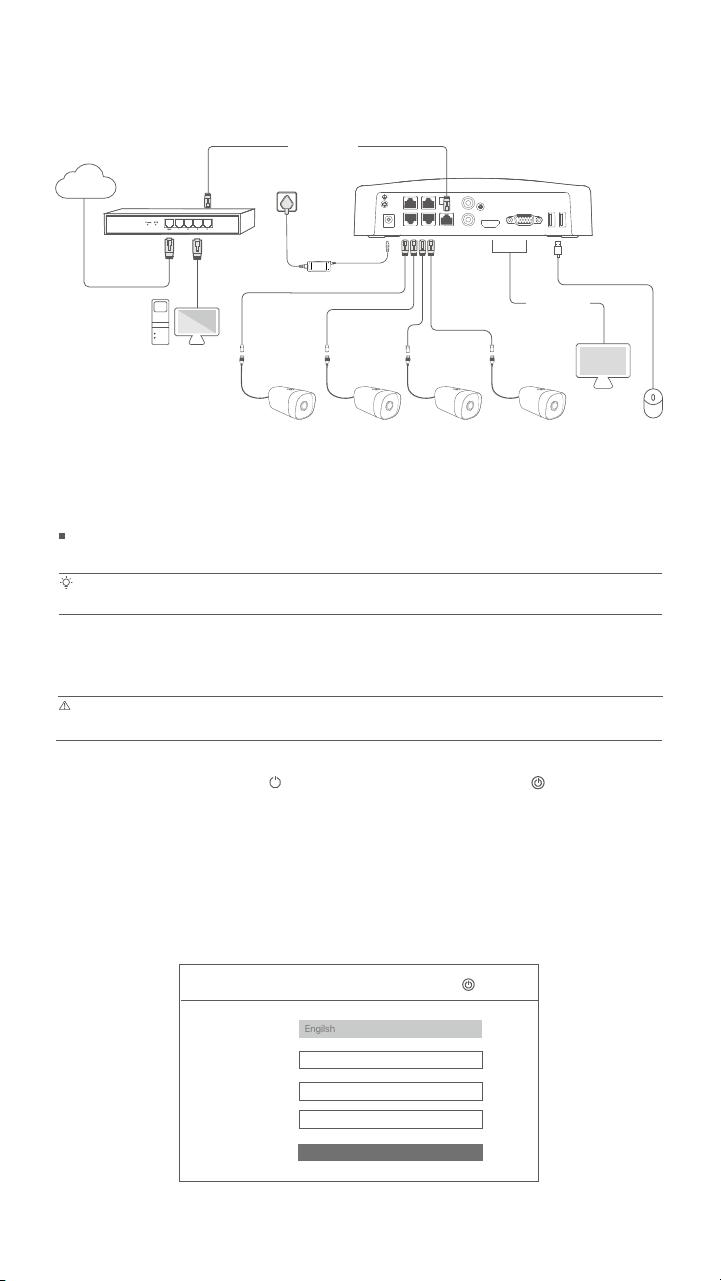
IV Basic configuration
Quick setup
After connecting the mouse and monitor to the NVR, you can perform quick setup.
Select the language displayed on the GUI and the time zone in which the NVR locates, and then click
OK.
Startup
Local management
Connect the included power adapter to the power port of the NVR, and plug the power adapter into the
power socket to start up the NVR.
Use the included power adapter to power on the NVR. The NVR may fail to work normally or even be damaged due to abnormal power supply.
Shutdown
Note
Note
Do not directly cut off the power supply of the NVR to force a shutdown; otherwise, the HDD may be damaged, videos may be lost, or even the
NVR may be damaged.
Initial Setup
(UTC+8:00) Beijing, Chongqing, H
Language
Time Zone
Date
Time
OK
Engilsh
Shutdown
After connecting the mouse and monitor to the NVR, perform the following settings on the NVR's web UI
(exit the Full Screen interface): Click in the upper right corner, click Shutdown , and then click OK.
When The Device is Shut Down. Please Cut Off the Power appears on the screen, unplug the power
adapter of the NVR.
III Connect the device
Computer
OUT
POWERPOWER PoE PORTS LAN AUDIO HDMI
1 3
2 4
VGA USB1 USB2
IN
Router
LAN
LAN
PoE NVR
WAN
LAN
Internet
Monitor
PoE
Ethernet cable
HDMI cable
or VGA cable
The K4P-4TR kit is taken as an example here.
PoE Camera PoE Camera PoE Camera PoE Camera
2022 - 01 - 14
11 : 26 :51

- 6 -
Set Password, enter your Email Address, and then click Activate.
Device Activation
8 to 32 characters
Re-enter the login password
Only for resetting the password
User Name
Password
Confirm Password
Email Address
Activate
admin
Shutdown
Unlock Pattern Network Cloud
Draw an Unlock Pattern
Redraw
Do Not Use Unlock Pattern
If you want to use a pattern to unlock the web UI, draw an unlock pattern. Otherwise, click Do Not Use
Unlock Pattern and skip to step .
ConnectedConnection Status
IP Address
Subnet Mask
Default Gateway
Unlock Pattern Network Cloud
Previous Next
DHCP
Tips
Ensure that the connection status is Connected, then click Next.
Ensure that the LAN port connection of the NVR is normal.
Ensure that the DHCP server function of the router to which the NVR is connected is enabled.
−
−
If the connection status is Disconnected, try the following solutions:

- 7 -
Tips
Ensure that the cloud status is Online and click OK.
−
−
If the cloud status is Offline, please ensure that the router to which the NVR is connected can access the internet and the filter function is
disabled.
You can also manage the NVR through the TDSEE App. Please refer to App management in this guide for details.
OnlineCloud Status
Previous OK
Unlock Pattern Network Cloud
Scan the QR Code to Download TDSEE App Scan the QR code with the TDSEE App to add the device
If you want to add the NVR to TDSEE App, please operate within 30 minutes
after the device is connected to the cloud; Otherwise, please reboot the
device and try again.
Settings completed. You can perform such operations as previewing real-time video, playing back the
recording and managing monitoring devices.
Run the TDSEE App and follow the instructions to complete user registration. Enter the homepage, then
tap Add a device or in the upper right corner of the homepage.
App management
Tips
After the cloud service of the NVR is enabled and the cloud status is Online, you can add and manage
the NVR through the TDSEE App.
To ensure that the login password of the NVR can be reset through the TDSEE App, please register using the email address you used to activate
the NVR.
Scan the QR code on the label at the bottom of the NVR or scan the QR code on the Cloud
Service page, then follow the instructions in the App.
After adding the NVR, you can remotely preview real-time video, play back the recordings and check
alarm messages through the TDSEE App.
23$PEF
0S
Download the TDSEE App.
After the smartphone is connected to the internet successfully, download and install the TDSEE App
onto your mobile phone by scanning the QR code or by searching for TDSEE in Google Play or App
Store.
Ensure that the NVR is powered on and working properly.
Tabla de contenidos
Idiomas:
Otros manuales de Sistema de seguridad de Tenda

Manuales populares de Sistema de seguridad de otras marcas


EDM
EDM Solution 6+6 Wireless-AE Manual de usuario

Highway Safety Group
Highway Safety Group EA401 Manual de usuario

Siren
Siren LED GSM Manual de usuario

Detection Systems
Detection Systems 7090i Instrucciones de montaje

Se-Kure Controls
Se-Kure Controls MicroMini SK-4841 Manual de usuario

Siemens
Siemens FDM273 Manual de usuario