t
t
t
power supply (24
to
56Vdc).
In
either
case,
the
polarity
of
the
input
power
voltage
is
immaterial,
as
the
full-wave bridge
rectifier
provided in these
Assemblies
serves
as
a
polarity
guard
for
input
dc
potentials. It
is
important,
however,
that
the
local
dc power supply
be
ungrounded when
used
with
these Assemblies, and
that
agood connection be
made
from
the ground lug on
the
apparatus
case
to
areliable source
of
local ground. (This ground con-
nection
is
especially
important
when
the
4008
is
used
in a248RFAssembly at a
transmitter
site,
where high RF fields
are
encountered.)
option
selection
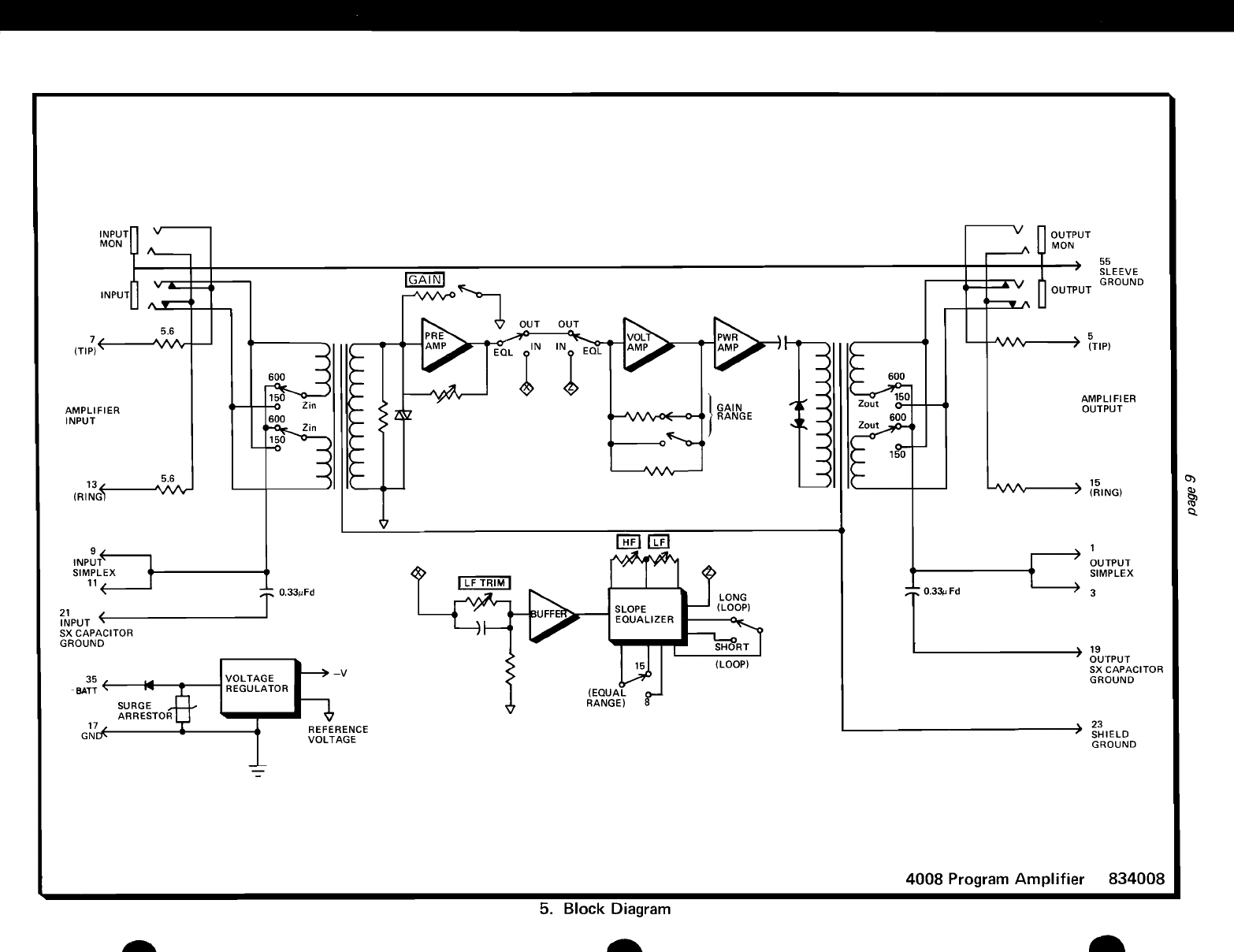
3.07 Six
option
switches must be set before
the
4008
is
aligned. These switches and
their
functions
are
described in paragraphs 3.08
through
3.12.
locations
of
these switcheson the moduIe's printed
circuit
board
are
shown in
the
condensed alignment,
figure
5.
3.08
Two
switches, labeled Z
IN
and Z
OUT,
are
set
to
select the 4008's
input
(Z
IN)
and
output
(Z
OUT) impedances. These switches select
either
150-ohm
or
600-ohm impedance-matching options.
In general, the 150-ohm
option
is
used
to
interface
nonloaded cable, while
the
600-ohm
option
is
used
to
interface broadcast equipment. (The 150-ohm
impedance-matching position provides anominal
degree
of
slope equalization
for
nonloaded cable.)
ICaution:
If
the 600-ohm impedance option
is
selected, the inputand
output
connections to the
4008
must
bebalanced
if
the midpointcapacitors
are
grounded. Response measurements using un-
balanced instruments will be in error.
If
150-
ohmimpedance
is
used, the unit
may
be
connect-
ed
to either balanced or unbalanced source and
load terminations.
bandwidth
3.09 The bandwidth-selection switch
is
set
for
the program application in which
the
4008
is
to
be
used.
The
8kHz-option
is
selected when
the
4008
is
used
in standard
am
radio
or
television
audio applications, while
the
15kHz-option
is
selected when
the
4008
is
used
in
fm
radio
applications.
equalization
3.10
The EQUALswitch
is
set
to
enable
or
dis-
able the 4008's integral equalization
circuitry.
In
applications where equalization
is
required, set
the
EQUAL
switch
to
the
IN
position
to
enable
the equalizer. In applications where equalization
is
not
required, set
the
EQUAL
switch
to
the
OUT
position.
3.11
If
equalization
is
used, the
LONG
LPSI
SHT
LPS switch must also be set
to
configure
the
equalization
shape
for
either long
or
short loops.
Set this switch
to
the
LONG
LPS position
if
the
unequalized
facility
loss
at
the
upper band
edge
page
5
(either
8kHz
or
15kHz) exceeds 17dB,
or
to
the
SHT
LPS position
if
facility
loss
at
8kHz
or
15kHz
is
less
than 17dB.
gain
3.12
Switch
selection
of
either
the
0
to
10dB,
10
to
20dB,
20
to
30dB,
or
30
to
40dB gain range
is
accomplished
by
setting
the
four-position
GAIN
RANGE
DIP switch
as
indicated in table 6. (Fine
adjustment
within
the selected 10dB range
is
made via
the
front-panel gain
potentiometer
dur-
ing alignment
of
the
module. This
potentiometer
is
continuously
adjustable over arange
of
approx-
imately
11dB
to
ensure overlap
of
the
major
gain
increments.) Switch positions
are
identified
as
left,
center, and right, rather than
by
number,
be-
cause
the
numbering
of
switch positions
by
the
various switch manufacturers
is
not
consistent.
The
left
position refers
to
the
leftmost
switch po-
sition
as
the
module
is
viewed
from
the
connector
end; center refers
to
the
next
adjacent switch po-
sition,
etc. If equalization
is
not
used, refer
to
the
circuit
level record
(elR)
card and set
the
GAIN
RANGE
switch
for
the
10dB range
that
encom-
passes
the required transmission level. If equaliza-
tion
is
used,
initially
set the
GAIN
RANGE
switch
for
the
10
to
20dB range, and reset
the
switch
(if
required)
after
equalization
is
completed. (Selec-
tion
of
the
10
to
20dB range
will
introduce suf-
ficient
gain
to
overcome
the
loss
inherent in
the
equalizer, thus ensuring accurate equalization.)
Again, precise level adjustment
will
be
made via
the
gain potentiometer.
special note:
In
some
rare
applications,
it
may
be
necessary to operate
or
test acircuit with a
4008
at
very high input levels -
beyond
the
specified +10dBm maximum input. (This
may
be the
case
when aradio station performs
de-
viation and modulation tests or frequency runs.)
While
input
levels
below
+10dBm will
not
pro-
duce distortion through the 4008,
input
signals
between +10dBm and +20dBm
may
produce
overload distortion unless the following pre-
cautions
are
taken:
1)
Use
the
Short
loops
(SHT
LPS)
option
for
all loops
with
1000Hz insertion
loss
below
about
5dB (measured between 600-ohm source
and load impedances).
2) Always set
the
GAIN
RANGE
switch
for
the
0
to
10dB range whenever
the
4008
is
oper-
ated in
the
SHT
LPS mode. This gain step over-
comes
loss
inherent in
the
equalizer in the
SHT
LPS mode.
·3) Whenever practical,
attempt
to
arrange
sig-
nal levels and
amplifier
gain
so
that
gain
intro-
.duced
by
the
front-panel 1
OdB
gain
potentiome-
ter
is
minimized
(fully
counterclockwise). This
means
that
gain should
be
introduced via the
10dB GA
IN
RANGE
switch especially in relative-
ly
short
loop
applications.