Telecrane F24+ Series Manual de usuario

1
F24+ Series Radio Remote Control
User Manual

2
WARRANTY
LIMITED WARRANTY
TELECRANE guarantees that this product meets its published specifications at the time of shipment
from the factory. Under proper installation it should work as expected. However, TELECRANE cannot
guarantee that operation in TELECRANE system is absolutely error-free, or without interruption.
Warranty period
This equipment is warranted against defects in material and manufacturing for a period of one year
from the date of shipment. During the warranty period, TELECRANE is responsible for necessary repairs
as long as the product can be proven to be defective.
For warranty service or repair this product must be returned to the service facility designated by
TELECRANE. Buyer will pay shipping charges to TELECRANE while TELECRANE will bear return shipping
charges.
Excluded Items
This warranty does not include consumable parts such as batteries, fuses, buttons, and relays. Also this
warranty does not cover failure or damage resulting from misuse, accident, unauthorized modification,
unsuitable operating environment, natural disasters, improper software setting or improper
maintenance.
Limitation of liability and remedy
If your TELECRANE product fails to work as warranted above, TELECRANE maximum liability under this
limited warranty is expressly limited to the lesser of the price you have paid for the product.
TELECRANE disclaims any liability as a result of any direct/indirect, special, incidental or consequential
damages.
Remarks
No other warranty is expressed or implied, except for the above mentioned. Any use of this remote
control product would be regarded the same as agreed to all clauses within this user manual.
ATTENTION
Please carefully read the manual before installing and operating this device.
Due to the complex nature of this equipment, it is necessary to read the entire manual before
installation.
The equipment has been stringently tested for quality assurance before delivery from factory.
However, it must not be used in extremely dangerous situations, or where damage may result.
After operation, shut off crane main power, receiver power, and remove transmitter key.
After operation, by pressing “STOP” pushbutton switches off receiver unit then keeping the
transmitter in a safe place when not in use to avoid any unintentionally operation.
The crane should be equipped with main power relay, limit switch and other safety devices.
Do not use this device during electrical storm or where there are conditions of high electrical
interference.

3
Make sure that the batteries are in good condition and power for receiver is correctly supplied.
The installation and maintenance service is allowed only when the receiver power is disconnected to
avoid electrical shock.
The contents of this manual may be amended by the manufacturer without notice.
The specification and function of remote is subjected to change without notice by manufacturer.
PRECAUTIONS
Operating in an industrial facility is relatively dangerous; therefore, operator must have taken the
adequate trainings in using F24+ system.
Besides obtaining qualification certificate for operating this remote control product, users must also
be both physically and mentally in well conditions, and has sufficient knowledge with safety
precaution.
Although F24+ transmitters are solid made for certain level of impact and weathering resistance, but
any malicious destruction or improper use might still cause high possibility of potential damage.
When transmitter battery power is low (Red LED), a STOP signal will be sent to receiver automatically
to turn off receiver. The batteries must be replaced immediately.
If the severe interference occurred, the operation must be stopped immediately.
Please remove the batteries when the equipment will not be used for a long time.
Be sure to know the "Procedures of Emergency" as follows.
PROCEDURES OF EMERGENCY
In case of an Emergency, please follow the procedure below and contact authorized distributor for
service immediately.
Press "EMS" button
Turn the key to "OFF" position and remove it.
Switch off crane main power.
Contact authorized distributor for inspection.

4
Chapter 1 F24+ TRANSMITTER & RECEIVER OVERVIEW
How to Start
Pre-inspection
1. There is e-card on both transmitter and receiver. Make sure the e-card is correctly installed.
2. Place 4 AA batteries with correct direction. And lock the battery cover.
Note:Before placing the batteries, make sure the Rotary KEY is on the OFF position
3. Turn on the transmitter. (Turn the EMS button clockwise and switch rotary key to ON position then
press START button)
4. Press function button for operation.
5. To switch off the transmitter/receiver, please follow the procedure below
a) Press EMS button.
b) Switch rotary key to off position and remove the KEY from transmitter.
c) Remove the batteries when the equipment will not be used for a long period of time.
e-Card on Transmitter e-Card on Receiver
5
Transmitter LED indicator
Three stages power indicator
1. Green color (Full power): Operate as usual.
2. Yellow color (Mid Power): Stop operation until new batteries are replaced.
3. Red (Low Power): A Stop signal will be sent to receiver automatically to turn off receiver. To avoid
the interruption during operation, check battery power frequently.
Inspection & Troubleshooting
Inspection
The daily inspection is highly recommended for safety reason. The inspection includes EMS Button,
Rotary Key and all other relevant functions. Stop the operation immediately when any error occurs and
resume to work until the error is being removed.
Transmitter LED Indicator
Transmitter red LED indicator blinking (Fast)
Pushbutton Jammed
Power-On without releasing EMS button
Not correct Power-On procedure
Transmitter red LED indicator blinking (Slow)
Low battery power, replace new batteries immediately
Transmitter red LED indicator remain ON
Check transmitter e-Card if is correctly installed
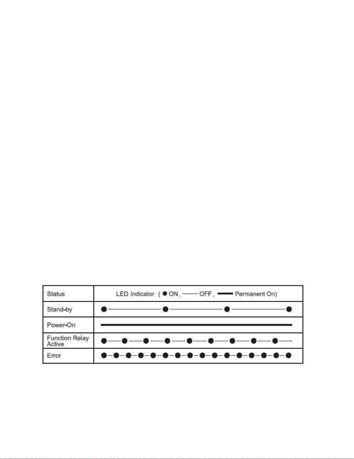
Receiver LED Indicator
The receiver LED indicator provide the messages to the operator as below
Receiver relay module LED3 blinking
Check receiver e-Card if is correctly installed

6
Specification
General Specification
Frequency:430.00 ~ 438.00 MHz
ID Code:4.3 Billions sets
Channel Space:50KHz
Hamming Distance :>20
Structure:Fiberglass reinforced plastic materials
Operating Temp.:-30℃~ +85℃
Operating Distance:Up to 100 Meters
Transmitter
Power:AA Battery x 4
Emission Power:< 10mW
Pushbutton:Single/Double Steps
Dimension:245x61x51 mm
Weight:Approx. 255g (without battery)
Receiver
Power:(1) 24/36/42/48/110/220/230/380 VAC (50/60Hz), tolerance ± 20% (2) 12~24VDC
Sensitivity:-110dbm
Relay:5A/250VAC
Dimension:Approx. 234x116x130 mm
Weight:Approx. 1240g (without cable)
7
CHAPTER 2 INSTALLATION & SETTING
Installation Precaution
Switch off receiver and keep power disconnected during installation to avoid electrical shock.
Keep away from spark (such as electrical motor, relay contactor, power line or any high voltage
devices) during receiver installation.
Receiver should be properly installed to prevent from loosing or dropping on the ground.
Check the power setting and relay configuration before installing the receiver.。
Installing the receiver unit inside the control box is prohibited. It is appropriate to install the receiver
outside the control box.
F24+ provides 4.3 billion sets of ID codes. Each unit has a unique ID code address. For safety reason,
please check the ID code again during installation if any other remote control device nearby.
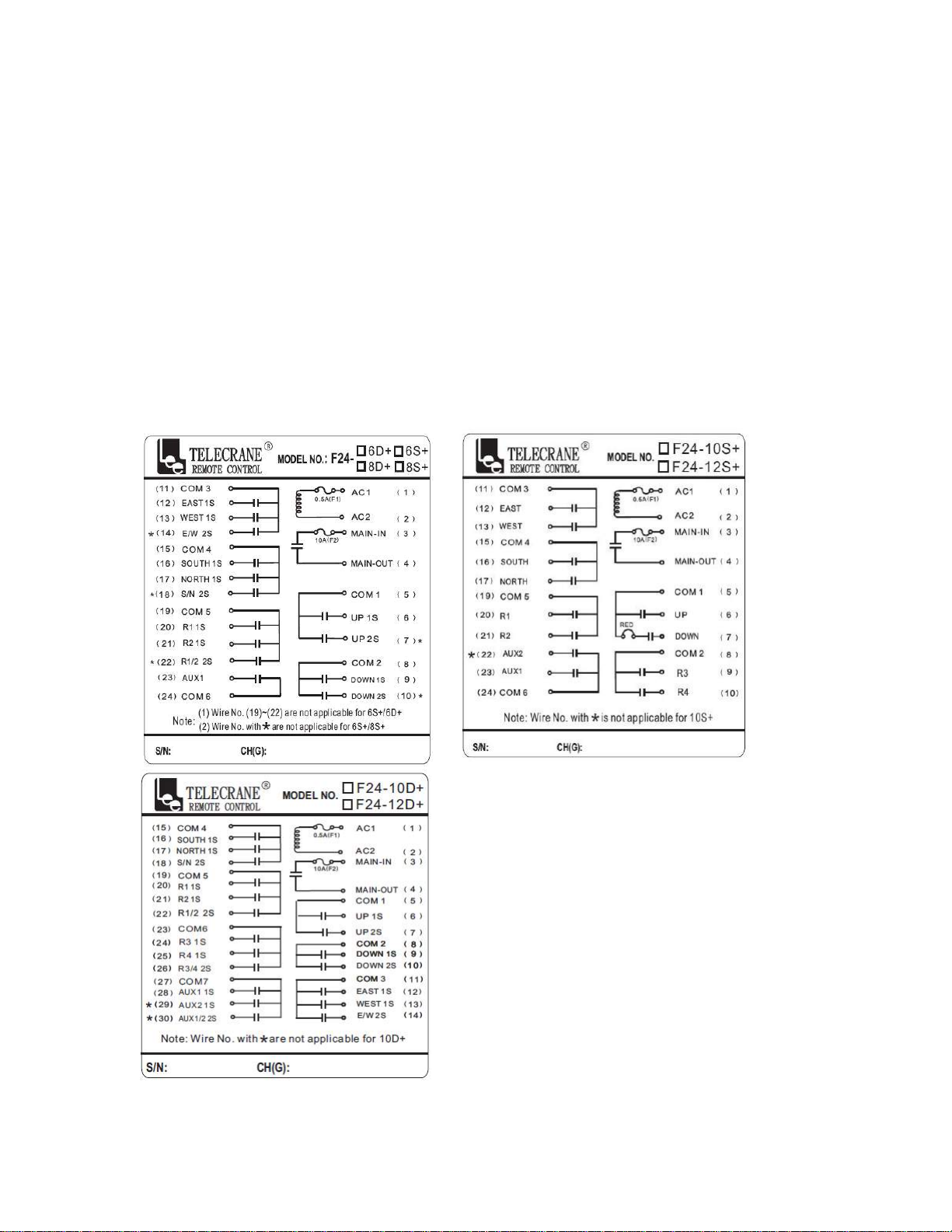
Wiring Diagram

8
Receiver power voltage selection
F24+ receiver provides transformer with 3 stages (i.e. 48VAC/220VAC/380VAC) that allows user to
change input power on site. The designated voltage had been preset by the factory.
Changing input power
1. Disconnect receiver power.
2. Unplug the connector (Fig. A)
3. Re-plug the connector into the new power position (Fig. B)
4. Completed
(Fig. A) (Fig. B)
Function Setting
F24+ remote control system can be set according to the working condition and operator’s need for the
following purposes: Specific pushbutton function, EMS neglected function, Auto-off time, Interference
neglected time…etc.
This enables the remote controller to perform the most effective operation and to provide the safest
operation. Please refer to the Software Function Setting in Chapter 3, next chapter.
Note: In addition to the PC software, the transmitter provides e-Card copy function which makes
easy, quick copying features without using software.

9
Chapter 3 SOFTWARE & COPY FUNTIONS
F24+ series PC Software Installation
1. Insert F24+ CD into CD-ROM Drive, the “auto-run” program will be pop up automatically.
2. Click “Next “for continue installation.
3. Click “Install”

10
4. Click "FINISH" for complete the installation.
USB Driver Installation
1. Go back to the F24+ series PC program file, install “PL2303_Prolific_DriverInstaller_V.1.8.0”.
2. Double click PL2303 installer icon then the USB Driver program will be installed automatically.
How to use F24+ series PC program
Reading / Writing the e-Card
1. Before using F24+ software, check the COM port number which is being occupied by the USB
cable. You may find the COM port number from Control Panel/System/Hardware/Device
Manager.
Tabla de contenidos
Otros manuales de Mando a distancia de Telecrane

Telecrane
Telecrane F21-2S Manual de usuario

Telecrane
Telecrane F21-12S Manual de usuario

Telecrane
Telecrane F21-E1 Manual de usuario

Telecrane
Telecrane F21-E2 Manual de usuario

Telecrane
Telecrane F25 Manual de usuario

Telecrane
Telecrane F24-12S Manual de usuario

Telecrane
Telecrane F24-60N Manual de usuario

Telecrane
Telecrane F24 Series Manual de usuario


