TECHWELL
TW88XX
TECHWELL, INC. 9 10/20/2008
User’s Manual:
c) USB -> SPI
This mode is similar to I2C mode. The PC will be the master device on the SPI interface.
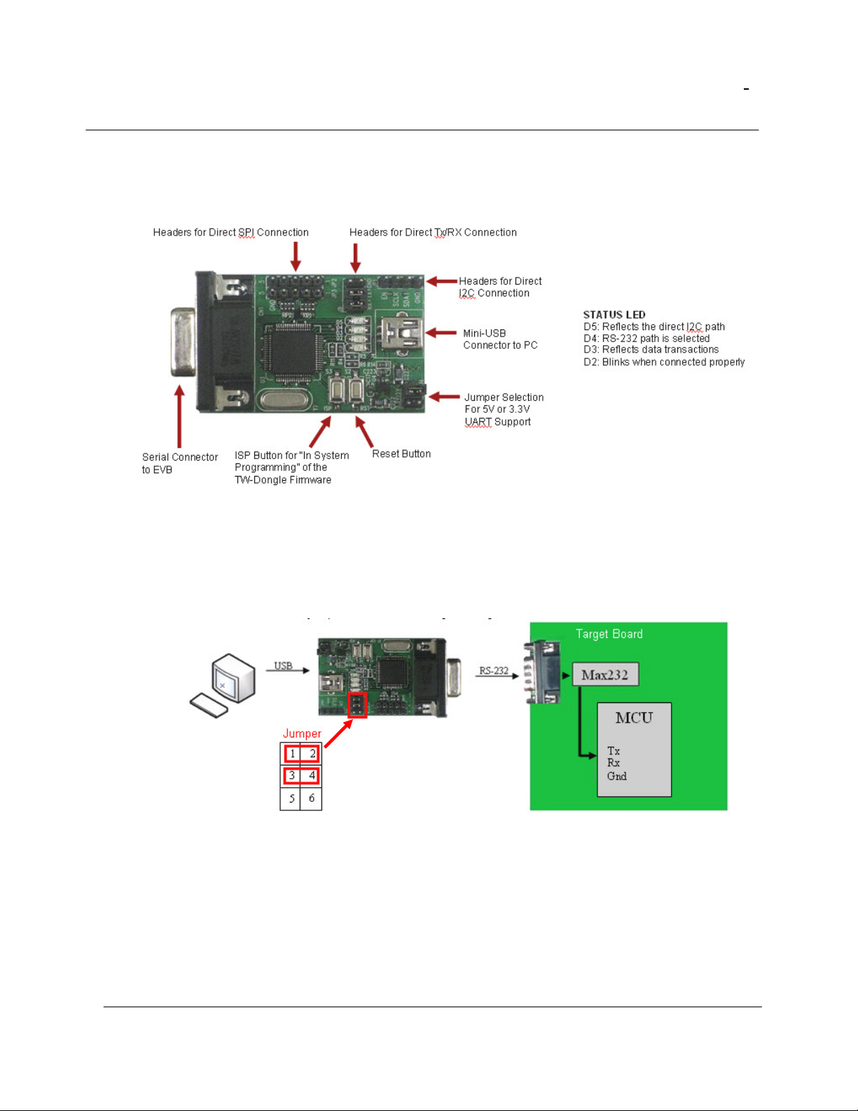
Pin Assignment (Used to Interface with Techwell’s Evaluation Boards)
JP3 JP2
Pin1: SPI_CSN (P0) (P4)
Pin2: SPI_SDI (P1) WP_N (P5)
Pin3: SPI_CLK (P2) RESET_N (P6)
Pin4: SPI_SDO (P3) MCU_EN(P7)
Pin5: Ground Ground
The TW_Dongle supports programming SPI flash memory if it is running firmware released on
2007/8/3 or later. The details of this procedure will be described in the next section for TW_Dongle
firmware updating. The SPI flash programming is useful in our TW88xx products that have an
embedded MCU.
When firmware upgrade is selected in the TW_Terminal application, the TW_Dongle mode will
automatically switch to SPI mode because it will need to download the firmware to SPI flash memory.
Again, there may be multiple bus masters and arbitration is required. To be able to access the SPI
flash using the TW_Dongle, the internal MCU in TW88xx should be disabled via the MCU_EN pin.
TW_Terminal provides the control for MCU_EN signal via pin 4 of JP2. During SPI programming
mode, this signal is held “low’ and is released to ‘high’ after programming is complete. The MCU will
start running the program without the need for another reset control.