Technische Alternative FRISTAR3 Manual de usuario

ta.co.at
FRISTAR3
FRESH WATER STATION
Operating manual
EnglishManual Version 1.02.4


3
Table of contents
Safety instructions . . . . . . . . . . . . . . . . . . . . . . . . . . . . . . . . . . . . . . . . . . . . . . . . . . . . . . . . . . . . 4
Disposal . . . . . . . . . . . . . . . . . . . . . . . . . . . . . . . . . . . . . . . . . . . . . . . . . . . . . . . . . . . . . . . . . . . . . . . . . . . . . .4
Mode of operation . . . . . . . . . . . . . . . . . . . . . . . . . . . . . . . . . . . . . . . . . . . . . . . . . . . . . . . . . . . . . 5
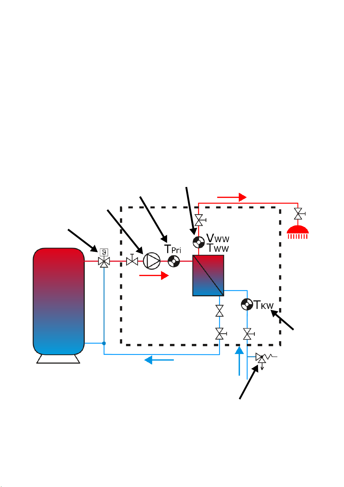
Hydraulic circuit diagram . . . . . . . . . . . . . . . . . . . . . . . . . . . . . . . . . . . . . . . . . . . . . . . . . . . . . . . . . . . . . . . . .5
Components . . . . . . . . . . . . . . . . . . . . . . . . . . . . . . . . . . . . . . . . . . . . . . . . . . . . . . . . . . . . . . . . . 6
Installation . . . . . . . . . . . . . . . . . . . . . . . . . . . . . . . . . . . . . . . . . . . . . . . . . . . . . . . . . . . . . . . . . . 7
Preparation . . . . . . . . . . . . . . . . . . . . . . . . . . . . . . . . . . . . . . . . . . . . . . . . . . . . . . . . . . . . . . . . . . . . . . . . . . . .7
Special accessories: VMS pre-mixing set . . . . . . . . . . . . . . . . . . . . . . . . . . . . . . . . . . . . . . . . . . . . . . . . . . . .7
Dimensions . . . . . . . . . . . . . . . . . . . . . . . . . . . . . . . . . . . . . . . . . . . . . . . . . . . . . . . . . . . . . . . . . . . . . . . . . . . .8
Interchanging connections . . . . . . . . . . . . . . . . . . . . . . . . . . . . . . . . . . . . . . . . . . . . . . . . . . . . . . . . . . . . . . . .9
Installation . . . . . . . . . . . . . . . . . . . . . . . . . . . . . . . . . . . . . . . . . . . . . . . . . . . . . . . . . . . . . . . . . . . . . . . . . . .10
Commissioning . . . . . . . . . . . . . . . . . . . . . . . . . . . . . . . . . . . . . . . . . . . . . . . . . . . . . . . . . . . . . . 10
Connection of a circulation line . . . . . . . . . . . . . . . . . . . . . . . . . . . . . . . . . . . . . . . . . . . . . . . . . . 11
Activating the DHW circulation pump using the FRISTAR3 controller . . . . . . . . . . . . . . . . . . . . . . . . . . . . . .11
Hydraulic circuit diagram with circulation line . . . . . . . . . . . . . . . . . . . . . . . . . . . . . . . . . . . . . . . . . . . . .11
Circulation pump (optional) . . . . . . . . . . . . . . . . . . . . . . . . . . . . . . . . . . . . . . . . . . . . . . . . . . . . . . . . . . .11
Activating the DHW circulation pump using a different switching device . . . . . . . . . . . . . . . . . . . . . . . . . . .11
Cascade switching . . . . . . . . . . . . . . . . . . . . . . . . . . . . . . . . . . . . . . . . . . . . . . . . . . . . . . . . . . . . 12
Hydraulic circuit diagram of a cascade with four FRISTAR3 fresh water stations . . . . . . . . . . . . . . . . . .12
Control with UVR67 . . . . . . . . . . . . . . . . . . . . . . . . . . . . . . . . . . . . . . . . . . . . . . . . . . . . . . . . . . . . . . . . . .13
Control of cascade switching with freely programmable controllers . . . . . . . . . . . . . . . . . . . . . . . . . . . .14
Cascade switching with circulation line . . . . . . . . . . . . . . . . . . . . . . . . . . . . . . . . . . . . . . . . . . . . . . . . . . . . .14
Schematic diagram for activating the DHW circulation pump with the FRISTAR3 controller . . . . . . .14
Schematic diagram for activating the DHW circulation pump with a different switching device . . . .15
Data transfer with DL bus . . . . . . . . . . . . . . . . . . . . . . . . . . . . . . . . . . . . . . . . . . . . . . . . . . . . . . . 16
Status (Index 13) . . . . . . . . . . . . . . . . . . . . . . . . . . . . . . . . . . . . . . . . . . . . . . . . . . . . . . . . . . . . . . . . . . . . . .17
For x2 devices . . . . . . . . . . . . . . . . . . . . . . . . . . . . . . . . . . . . . . . . . . . . . . . . . . . . . . . . . . . . . . . . . . . . . .17
For UVR67 . . . . . . . . . . . . . . . . . . . . . . . . . . . . . . . . . . . . . . . . . . . . . . . . . . . . . . . . . . . . . . . . . . . . . . . . .18
Electrical connection . . . . . . . . . . . . . . . . . . . . . . . . . . . . . . . . . . . . . . . . . . . . . . . . . . . . . . . . . . 19
Safety instructions . . . . . . . . . . . . . . . . . . . . . . . . . . . . . . . . . . . . . . . . . . . . . . . . . . . . . . . . . . . . . . . . . . . . .19
Operation of the controller and LED indicators . . . . . . . . . . . . . . . . . . . . . . . . . . . . . . . . . . . . . . . 20
Manual-automatic changeover switch . . . . . . . . . . . . . . . . . . . . . . . . . . . . . . . . . . . . . . . . . . . . . . . . . . .20
Status LED indicator . . . . . . . . . . . . . . . . . . . . . . . . . . . . . . . . . . . . . . . . . . . . . . . . . . . . . . . . . . . . . . . . .20
Pump LED indicator . . . . . . . . . . . . . . . . . . . . . . . . . . . . . . . . . . . . . . . . . . . . . . . . . . . . . . . . . . . . . . . . . .20
Technical data . . . . . . . . . . . . . . . . . . . . . . . . . . . . . . . . . . . . . . . . . . . . . . . . . . . . . . . . . . . . . . . 21
Pressure loss characteristic curve plate heat exchanger . . . . . . . . . . . . . . . . . . . . . . . . . . . . . . . . . . . . . . . .22
Pump curve . . . . . . . . . . . . . . . . . . . . . . . . . . . . . . . . . . . . . . . . . . . . . . . . . . . . . . . . . . . . . . . . . . . . . . . . . .22
Information on the Eco-design Directive 2009/125/EC . . . . . . . . . . . . . . . . . . . . . . . . . . . . . . . . . . . . . . . . .23
Plate heat exchanger corrosion resistance . . . . . . . . . . . . . . . . . . . . . . . . . . . . . . . . . . . . . . . . . . . . . . . . . .23
Tips on troubleshooting . . . . . . . . . . . . . . . . . . . . . . . . . . . . . . . . . . . . . . . . . . . . . . . . . . . . . . . . 24

4
Safety instructions
Intended use
The freshwater station may only be installed in heating systems between the buffer tank and the
drinking water circuit. The technical limit values specified in this manual must be considered.
Incorrect use will result in the negation of any liability claims.
Electrical connection
Any electrical connections must be made by qualified electricians. Connection cables must be rout-
ed in the recesses provided in the insulated base in such a way that direct contact with the pump
casing and the pipes is prevented.
Before switching on, check whether the supply voltage matches that stated on the power rating
plates of the pump and the controller. All connections must correspond to the local regulations. Be-
fore opening the controller, all poles of the power supply must be isolated.
If you are connecting the FRISTAR3 to an electrical system via a residual current device (RCD), use
an RCD of type A which will detect pulsating direct currents and bears the following marking:
Checking using a high voltage insulation tester may cause damage to the pump and the control elec-
tronics.
Safety standards during installation, commissioning and maintenance
Installation, commissioning and maintenance may only be carried out by qualified persons who are
familiar with these operating instructions.
Before you start work on the system, ensure that the system is switched off and all components are
cooled down. When replacing the pump, turn the 4 ball valves into the closed position.
In multi-occupancy dwellings, legionella protection must be observed in accordance with the local
regulations.
Disposal
• Devices no longer in use or beyond a state of repair must be disposed of in an en-
vironmentally responsible manner by an authorised collection point. They mus nev-
er be treated as ordinary household waste.
• We can undertake the environmentally responsible disposal of devices sold by the
Technischen Alternative company upon request.
• Packaging material must be disposed of in an environmentally responsible man-
ner.
• Incorrect disposal may result in considerable damage to the environment, as
many of the materials used require professional handling.
These instructions are intended exclusively for authorised professionals. To avoid
accidents and damage due to incorrect operation, carefully read through these op-
erating instructions before you start working with the freshwater station. If you
carry out any alterations to the construction of the freshwater station or the safety
devices, you may invalidate your right to make guarantee claims. Always observe
the local regulations.
WARNING! Dependent on the pump and system operating conditions, the surface temper-
atures can be very high. Direct contact with the pump or pipes can result in burns!

5
Mode of operation
Through use of the instantaneous heating concept, drinking water is heated both hygienically and
with low energy consumption in the FRISTAR freshwater station.
If water is drawn from the mains, the primary circuit pump transports tank water from a buffer tank
through the plate heat exchanger.
On the secondary side of the heat exchanger the drinking water flowing through is heated to the set
temperature. The cooled tank water is returned to bottom layer of the buffer tank.
The speed control of the primary circuit pump takes place in the FRISTAR3 controller based on the
readings from the volume flow sensor in the hot water line (flow rate VWW and temperature TWW)
and the temperature sensors in the cold water line (TKW) and the primary flow (TPri). The pump is
controlled with PWM signals. Optimal matching of the control behaviour with the pump, valve and
heat exchanger ensures perfect stabilisation of the outlet temperature.
The controller has an integral heat meter, which enables the values to be read via the data link.
Hydraulic circuit diagram
Pre-mixer (recommended)
Temperature
Primary flow
Flow rate sensor and DHW
temperature
Cold water temperature
Safety valve max. 6 bar
Primary pump

6
Components
Controller
Plate heat ex-
changer
Ball valve
Ball valve
Ball valve
Primary
sensor
Volume flow
sensor + DHW
temperature
Ball valve
Ventilation primary circuit
Cold water
sensor
Power cable
Flow primary
circuit
Return pri-
mary circuit
Hot water Sec-
ondary circuit
Cold water Sec-
ondary circuit
Valve
Pump
(Orientation of the
plug-in strip varies)

7
Installation
Preparation
• A safety valve (max. 6 bar) must be installed in the cold water supply corresponding to stand-
ards DIN 1988 and 4753, part 1 and TRD 721.
• If the cold water pressure > 6 bar, fit a diaphragm pressure reducer max. 6 bar.
• The installation of flushing equipment before and after the plate heat exchanger in the primary
and secondary circuits is recommended for descaling or cleaning as necessary.
Special accessories: VMS pre-mixing set
If the tank is operated at a temperature higher than 70 °C a pre-mixer that restricts the temperature
to less than 70 °C must be used in the primary circuit.
In order to prevent damage from calcification, the maximum pre-mixing temperature must be 70 °C
with a water hardness of up to 10 °dH, 65 °C with up to 15 °dH and 60 °C at most with a hardness
above 15 °dH.
The VMS pre-mixing set is suitable for both FRISTAR models (left pump, right pump).
Figure: Connection for FRISTAR with right pump
Technical data
Maximum temperature of pri-
mary circuit
95°C, short term: 100°C
Setting range 45°C - 65°C
Flow coefficient of mixing valve 4,5m3/h
Connections for FRISTAR ¾“

8
Dimensions
Housing dimensions (thermal insulation cover)
W x H x D = 366 x 573 x 160 mm

9
Interchanging connections
For optimum matching of the pipelines to the freshwater station it is possible to interchange the con-
nections (right/left). This does not change venting of the primary circuit, however.
Procedure:
1. Demounting of pipe elements 1 - 4 including pump from the heat exchanger
2. Removal of the pump and installation in the correct position.
3. Remount pump connection plug 5 on the other side. The flow direction of the pump is upwards.
On WILO pumps, the connection plug is above the pump, and on Grundfos pumps it is below.
4. Mounting of pipe elements 1 - 4 and the pump on the heat exchanger (see figures above) on the
other side, correct positional setup of the volume flow sensor
5. Commissioning according to the "Commissioning" chapter
Important: The primary and secondary connections must be exchanged together!
11
22
3
4
5
3
4
Pump connection-plug
Version
„Pump right“
Version
„Pump left“

10
Installation
• Mounting position: Only vertical
• Installation with the heat exchanger at the top/above the controller (acc. to diagrams) is recom-
mended.
• Pull off the cowling in a forwards direction.
• If necessary: Interchange the right/left connections (see chapter "Interchanging connections").
• Mark the fastening points, insert rawl plugs, fasten the station to the wall.
• Fitting and connection of the pipe connections (3/4" outside thread connector). Plan for as short
as possible pipes in the primary circuit (tank -> freshwater station).
• Check all the freshwater module's connections for leaks and ensure that they are securely fit-
ted.
• Electrical connection
The freshwater station is pre-wired ready for installation, connection to the electricity mains
takes place on site:
• using a plug in a wall socket or
• using a double pole isolator with a permanent connection.
Commissioning
• Before filling the system, thoroughly flush both the primary and secondary side systems.
•Slowly fill the house system with drinking water via the secondary side ball valves.
• Vent the house system at the draw-off valves.
• Slowly fill the system with hot water via the ball valves in the primary flow.
• Vent the primary circuit using the venting opening of the plate heat exchanger.
• Set the pump to continuous operation and check pump running. Audible background noise dur-
ing operation of the circulating pump indicates air in the system.
Warning! Only start the pump when it is filled.
• Check all connections, including in the freshwater station, for correct seating and leaktightness.
If necessary, retighten to the necessary torque.
• When using a circulation pump: Set the differential temperature at the potentiometer inside the
controller (Caution! Switch off the 230 V power supply before opening the controller!)
• Place the cowling on the bottom part
• Set the pump in automatic mode and select the setpoint temperature.
Tabla de contenidos
Otros manuales de Sistema de agua de Technische Alternative
Manuales populares de Sistema de agua de otras marcas

Spirotech
Spirotech SPIROVENT SUPERIOR S250 Manual de usuario

Culligan
Culligan Aqua-Cleer Aqua-Cleer Advanced Drinking Water... Manual de usuario

A.O. Smith
A.O. Smith Dura-Max AJH - 1000A - P Manual de usuario

Microline
Microline T.F.C.-4 Manual

Eureka Forbes
Eureka Forbes Aquaguard Select Manual de usuario

Cetetherm
Cetetherm AquaEfficiency Manual de usuario


