Technische Alternative ATON Manual de usuario

ta.co.at
ATON
ELECTRIC IMMERSION HEATER EHS-R
CAN ENERGY METER CAN-EZ3A
End user guide
English
Manual Version 1.25 (CAN-EZ3)
Manual Version 1.16 (EHS-R)

2
Table of contents
Principles . . . . . . . . . . . . . . . . . . . . . . . . . . . . . . . . . . . . . . . . . . . . . . . . . . . . . . . . . . . . . . . . . . . 3
Device overview . . . . . . . . . . . . . . . . . . . . . . . . . . . . . . . . . . . . . . . . . . . . . . . . . . . . . . . . . . . . . . . . . . . . . . . .3
General information on programming parameters . . . . . . . . . . . . . . . . . . . . . . . . . . . . . . . . . . . . . . . . . . . . . .4
Work settings . . . . . . . . . . . . . . . . . . . . . . . . . . . . . . . . . . . . . . . . . . . . . . . . . . . . . . . . . . . . . . . . 5
Function overview . . . . . . . . . . . . . . . . . . . . . . . . . . . . . . . . . . . . . . . . . . . . . . . . . . . . . . . . . . . . . . . . . . . . . .6
Overview . . . . . . . . . . . . . . . . . . . . . . . . . . . . . . . . . . . . . . . . . . . . . . . . . . . . . . . . . . . . . . . . . . . . . . . . . . . . . .6
Statistics – export to grid . . . . . . . . . . . . . . . . . . . . . . . . . . . . . . . . . . . . . . . . . . . . . . . . . . . . . . . . . . . . . .7
Statistics – import from grid . . . . . . . . . . . . . . . . . . . . . . . . . . . . . . . . . . . . . . . . . . . . . . . . . . . . . . . . . . . .7
Statistics – own consumption . . . . . . . . . . . . . . . . . . . . . . . . . . . . . . . . . . . . . . . . . . . . . . . . . . . . . . . . . .7
Heater 1 . . . . . . . . . . . . . . . . . . . . . . . . . . . . . . . . . . . . . . . . . . . . . . . . . . . . . . . . . . . . . . . . . . . . . . . . . . .8
Forced operation . . . . . . . . . . . . . . . . . . . . . . . . . . . . . . . . . . . . . . . . . . . . . . . . . . . . . . . . . . . . . . . . . . . . .9
Configuration . . . . . . . . . . . . . . . . . . . . . . . . . . . . . . . . . . . . . . . . . . . . . . . . . . . . . . . . . . . . . . . . . . . . . . . . .10

Principles
3
Principles
These instructions are aimed at the final user of the energy meter. For details about the device, pro-
gramming, etc., detailed operating instructions are available on our website www.ta.co.at or on the
official Technische Alternative wiki.
The CAN-EZ3A is a freely programmable energy meter, which communicates wirelessly with a vari-
able EHS-R immersion heater. The purpose of this device is to identify surplus output, e.g. from PV
systems, and convert this surplus into domestic hot water, instead of exporting it to the mains, which
can be less profitable.
The energy meter is operated via a display, a rotary dial and a button.
Device overview
The display (1) is used to navigate within the energy meter, to program functions, read in values, ac-
cess other devices, etc.
The dial (2) to the right of the display is used for navigation. A clockwise rotation moves you down
the menu; anti-clockwise moves you up.
Pressing the dial (2) opens the selected menu/allows you to change the selected value/parameter.
(= Enter button)
Pressing the button (3) below the dial will exit a menu. (= Back button)
Pressing "Enter" or "Back" relates to the value/menu item framed on the display.
The "Status" LED (4) above right of the rotary dial provides information on the status of the device.
Green flashing means the energy meter is starting up. A continuous green light shows normal oper-
ation. Orange means there is a "message", for example concerning a collector overtemperature shut-
down. Red means there is a "fault", such as a DL sensor failure.
Briefly pressing the reset button (5) restarts the device. For a total reset, press and hold the button
until the status LED (4) stops quickly flashing orange and starts slowly flashing red.
Principles
4
General information on programming parameters
for inputs, outputs, fixed values, functions, general settings, and CAN and DL inputs and outputs.
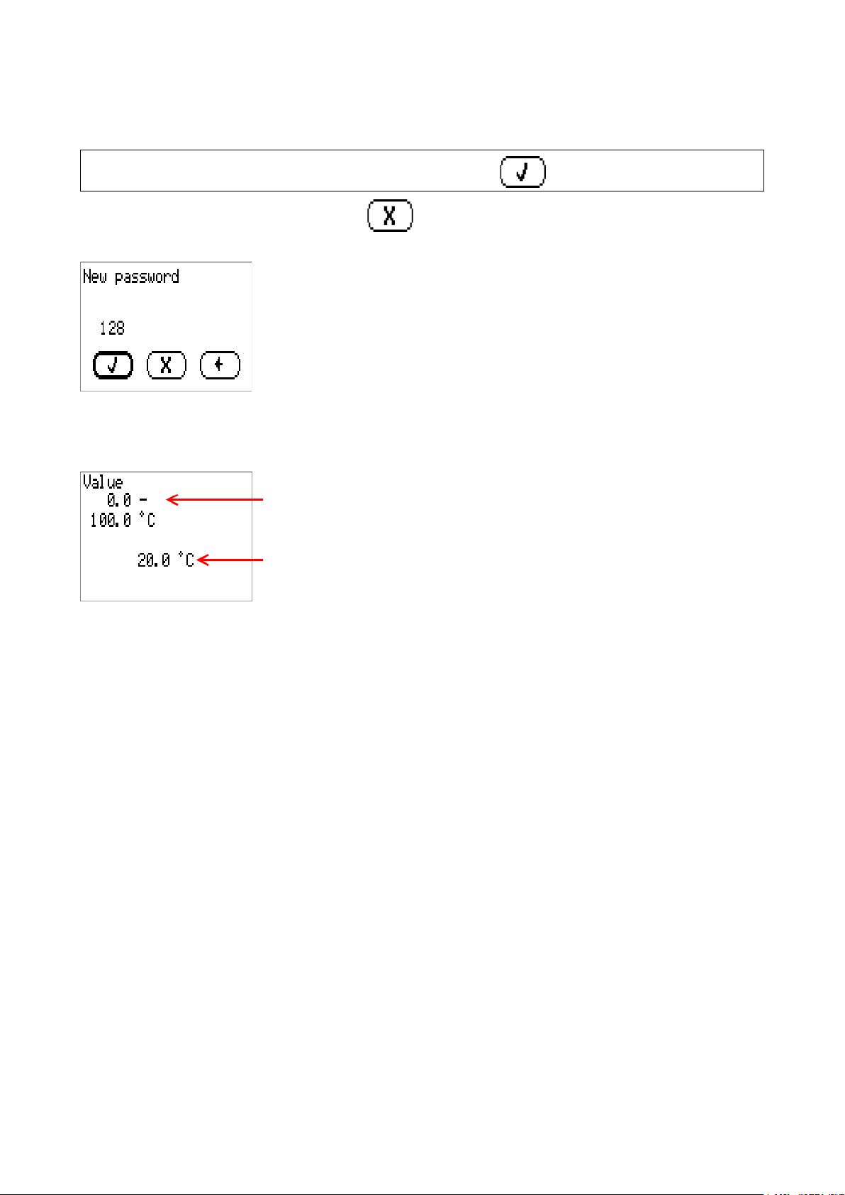
If you want to discard your entries, select .
Example:
Entering numeric values
The following window is displayed for entering numerical values:
Name of the numeric value, entry range
Current numeric value
The current value is shown (example: 20.0 °C).
The top line shows the name of the value, then the entry range (example: 0.0 – 100.0 °C).
The value is entered by turning the rotary dial. As there are no symbols for confirming or rejecting a
value, the entry is confirmed by pressing the dial or rejected by using the back button.
If displayed, entries must be confirmed with a .

User manual
5
Work settings
The essential function of programming is converting surplus output (e.g. from PV systems) into
DHW instead of less profitable export to the mains. An optional function is also available for heating
DHW with an immersion heater within a user defined time window (disabled at the factory). “Cylinder
temperature” in this case relates to the first sensor input on the immersion heater itself.
An energy meter also runs together with a date-specific memory for viewing meter readings and
yields.
The energy meter is programmed at the factory, including a function overview. If this has not been
changed, here are the instructions for various parameter settings.
These instructions relate to the factory programming and function overview.
As the energy meter is freely programmable, the displays on your device may differ in some cases
drastically from the figures in these instructions.
If the system malfunctions, it is generally advisable to contact the system installer. These instruc-
tions are not intended to be used for troubleshooting; instead, they should be used for customis-
ing the energy meter with factory programming to suit the requirements of the end user.

User manual
6
Function overview
The function overview referred to in these instructions can be ac-
cessed via the top item in the main menu called "Function overview".
Overview
Date and time
Temperature of the cylinder sensor, connected to the immersion heat-
er. If 9999.9 °C is displayed here, there is a sensor lead break. The sen-
sor may not have been fitted. This sensor is required for the basic
function of the immersion heater.
Power exported to/drawn from the grid. A positive value means that
this power is drawn from the grid. A negative value means that this
power is exported to the grid. Important: by default, 200 W is exported
to the grid before the immersion heater switches on.
Surplus power that is utilised by all consumers that the CAN-EZ3(A)
energy meter controls.
These entries are to links of other pages of the function overview. They
are described on the following pages of the instructions.

User manual
7
Statistics – export to grid
First, the power that is currently being exported to the grid is displayed,
followed by various meter readings.
At the bottom of the page is a button to reset the meter readings.
Statistics – import from grid
The next page is similar to the previous one, except that the meter readings are for power drawn from
the grid rather than exported to it.
Statistics – own consumption
This page is also similar to the two previous ones, except that it concerns the power that the immer-
sion heater expends. Surplus use and forced operation (DHW heating) are combined here.
User manual
8
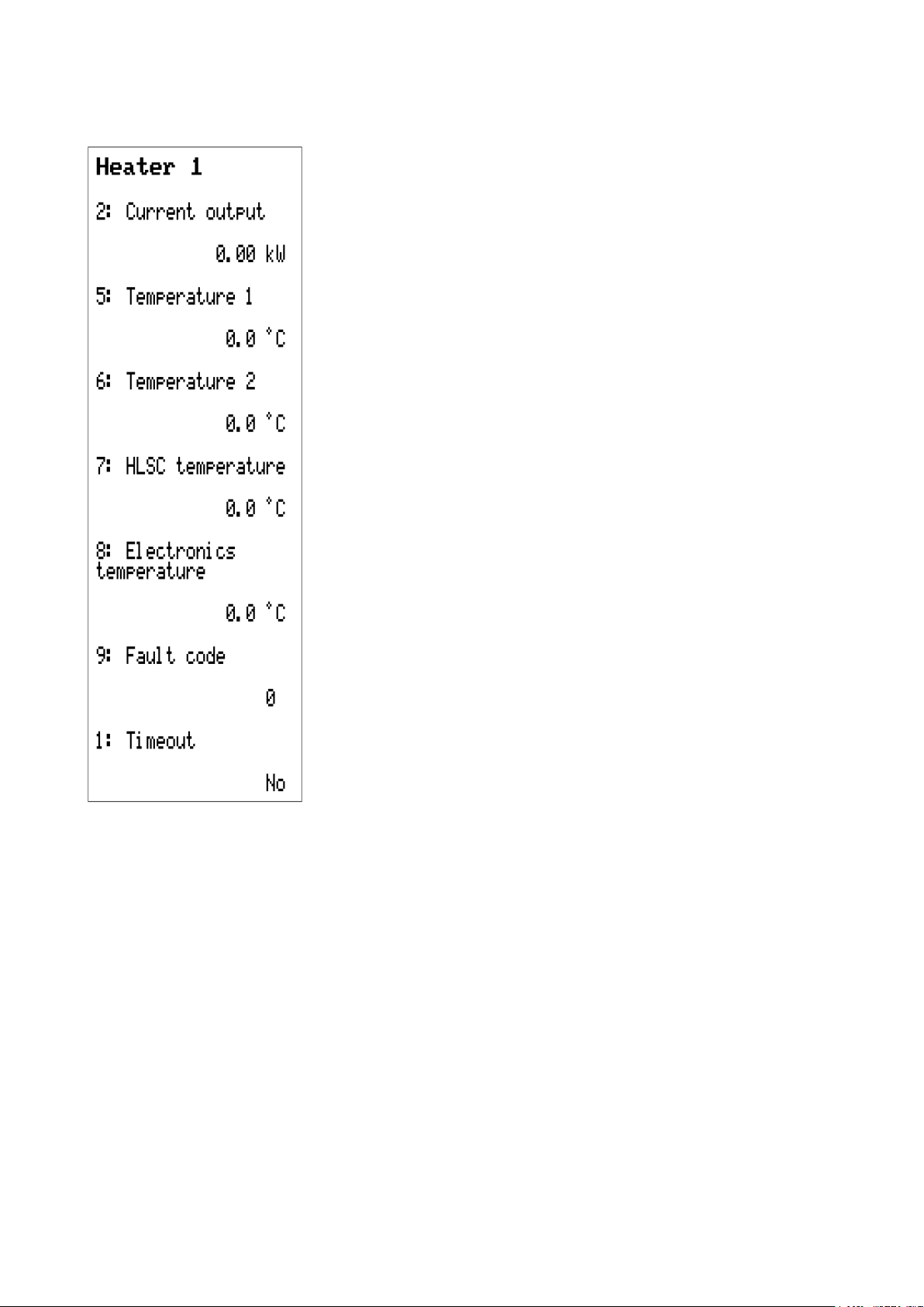
Heater 1
This page provides an overview of the immersion heater itself.
Power that the immersion heater is currently consuming.
Temperature of the cylinder sensor, connected to the immersion heat-
er. If 9999.9 °C is displayed here, there is a sensor lead break. The sen-
sor may not have been fitted. This sensor is required for the basic
function of the immersion heater.
Second temperature sensor – not set at the factory.
Safety temperature limit: If the temperature at the immersion heater it-
self reaches 95 °C, the immersion heater switches off and must be re-
started manually.
Temperature at the PCB of the immersion heater.
If there is an error, a number above 0 is displayed here. This number
provides information about the errors that have been detected.
If Timeout is set to “Yes”, the energy meter has lost the connection to
the immersion heater.

User manual
9
Forced operation
Forced operation is used for DHW heating, as the immersion heater is factory-set to only switch on
if surplus power is available, not on the basis of any particular temperature.
Switching on forced operation (shown in the illustration as currently
switched off)
Time programs for DHW heating (see below)
Required DHW temperature
Power used to switch the immersion heater on when forced operation
becomes active.
If this button is pressed, heating to the set temperature is carried out
once, regardless of the time programs and surplus power.
Time programs
The days with a black background are the ones on which this time pro-
gram is to be active. In the illustration, this program is active from Mon-
day to Friday.
On the days selected above, forced operation is active at the times set
here.
A second time program can be set, e.g. to define different times at the
weekend.

User manual
10
Configuration
On the last page of the function overview, a few more settings can be made.
Set output
This value indicates the power that is exported to the grid as tolerance
before the energy manager activates the immersion heater. This pre-
vents inadvertent power drawn, which could otherwise occur due to the
system inertia.
A value of -0.20 kW means that the immersion heater is only activated
at a surplus of >200 W.
Soft startup
The soft start is used to slowly ramp up to the power that the immersion heater consumes. It is rec-
ommended to set this setting to “Yes” if there is a battery storage unit in the system.
Max. temp. cylinder
Maximum temperature at the top of the cylinder, measured at the sensor connected directly to the
immersion heater. If the temperature set here is reached there, the immersion heater switches off
until the temperature falls 5 °C below it again.
Forced operation
Link to the “Forced operation” page, described on page 9.
Este manual sirve para los siguientes modelos
2
Tabla de contenidos
Otros manuales de Instrumento de medición de Technische Alternative


Manuales populares de Instrumento de medición de otras marcas


Endress+Hauser
Endress+Hauser Proline Promag 50 Especificaciones técnicas

Siemens
Siemens SITRANS F Coriolis FCT030 Manual de lista de piezas

KLINGER
KLINGER CMF V Series Manual de usuario

EXFO
EXFO FTB-2 Manual de operación y mantenimiento

Keysight
Keysight M8290A Manual de usuario

ADTEK
ADTEK MW-5 Manual de usuario