System 3 17-19
BH32 Behavioral Cage Controller
ReplicatinganExistingBehavioralControlSystem
The TDT system provides a unifying interface for sending and receiving behavioral
information from a behavioral control box without the need for the external devices
from these other companies.
TDT provides a default set up that uses standard Molex pins, an External power
source to drive high current and high voltage devices (such as feeders, water
delivery systems, foot shock systems, etc) or to accept inputs from such devices.
The hardware states of these particular interfacing devices are fixed and the BH32
bank directions and logic levels must be configured to match (see “Digital I/O ” on
page 17-19).
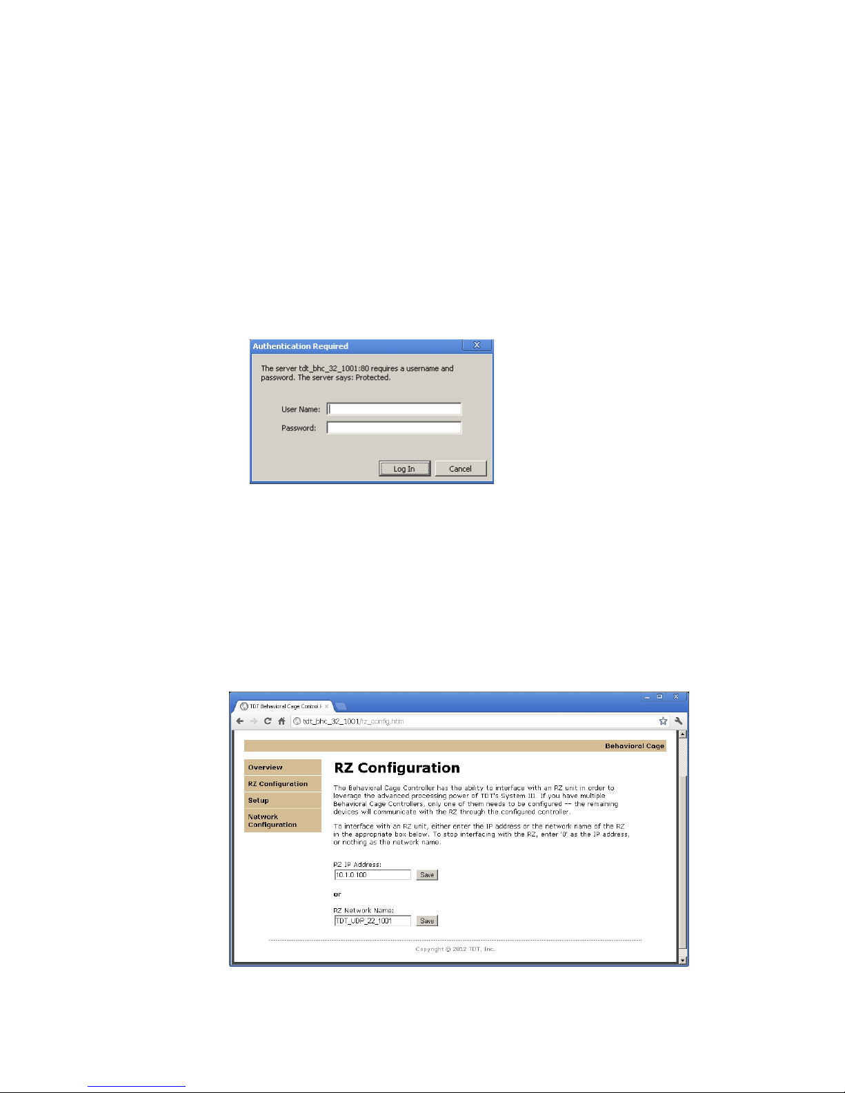
MoreComplexCustomSystemConfiguration
Information can be sent and received from the Molex interface in the following ways.
Note: Molex Banks A and B can be used as outputs and only outputs. Molex Bank D can
be used as inputs and only inputs. The direction and logic level of each bank is
configured through the BH32 web interface (See “Controller Configuration” on
page 17-23).
Important!: Attempting to drive an input from both the digital input and Molex connectors will
damage the device.
ControllingtheMolexoutputswithUDP/Serial(banksA&Bonly)
Configure the bank as an output. The Molex outputs are low when active. The digital
output logic is the inverse of the Molex output logic.
MonitoringtheMolexinputswithUDP/SerialandDigitalI/O(bankDonly)
Configure Bank D as an input. Active-Low means that when the Molex input is low,
the value is 1. The digital output logic mirrors the Molex input logic.
ControllingtheMolexoutputswithDigitalinputs(banksA&Bonly)
Configure the bank as an input, to bypasses the internal processor and control the
Molex lines directly. Molex output logic is the inverse of the digital input.
UsingDigitalandUDP/SerialI/Oonly
If the Molex connectors are not being used, then all four banks of digital I/O can
be used to send receive signals with the UDP/Serial interface with no restrictions on
bank direction.
DigitalI/O
The BH32 includes 32 bits of programmable I/O grouped in four 8-bit banks. Digital
I/O lines are accessed via the Digital IO–1 and Digital IO–2 25-pin connectors on
the back panel. Digital inputs accept +5V TTL inputs. Digital outputs are +5V. For
pinouts, see “BH32 Technical Specifications” on page 17-30.
StatusLights
A row of 32 status lights on the front panel report the state of the individual input/
output bits and are labeled to show banks A – D. When a bit is active, the
corresponding bit light glows red.