TCS QWL4.1 Manual de usuario

2800 Laura Lane • Middleton, WI 53562 |800.288.9383 |www.tcsbasys.com 202311
Building Automation Systems
Building Automation Systems
|Installation Manual
QWL4.1
Integrated Building Manager Panel

23
2800 Laura Lane • Middleton, WI 53562 |800.288.9383 |www.tcsbasys.com Building Automation Systems
23
Introduction ........................................................................................................3
Installation..........................................................................................................4
Glossary of Terms ..................................................................................................................................4
Material List.............................................................................................................................................6
Wall Mounting........................................................................................................................................6
Wiring Access Port ................................................................................................................................6
Factory IP Network Address Configuration......................................................................................6
Power and Communication Connections ........................................................................................ 7
Input Wiring............................................................................................................................................8
RS-485 Controller Network Wiring & Setup ..................................................................................10
Network Wiring..............................................................................................................................................................10
Three-Wire Network Wiring........................................................................................................................................ 11
Two-Wire Network Wiring........................................................................................................................................... 12
Startup ...................................................................................................................................................13
Troubleshooting ..................................................................................................................................14
Power LED Does Not Light Up .................................................................................................................................... 14
No Communications with Controllers on the Network ........................................................................................ 14
No LAN Link to the Internet ........................................................................................................................................ 14
No Communication with RS-485 Ports (COM 1 and 2), Ubiquity Time-out, or No Data................................. 14
Gateway Conguration ......................................................................................16
Introduction to Gateway Configuration .........................................................................................16
Gateway Configuration Via Laptop............................................................................................................................ 16
Gateway Configuration via CLI................................................................................................................................... 21
Lighting/Pulse Meter Programming....................................................................24
Introduction to Lighting/Pulse Meter Programming .................................................................. 24
Pulse Meter Module Programming ..................................................................................................27
Meter Types .................................................................................................................................................................... 27
Appendices.......................................................................................................29
Appendix A: Local Management Port ............................................................................................. 29
Connection Setup .........................................................................................................................................................29
Appendix B: Revert Back to DHCP Settings....................................................................................35
Appendix C: Monitor and Keyboard ............................................................................................... 39
Connection Setup .........................................................................................................................................................39
Appendix D: Configuring Local Management Port as a Fail-Over Port.................................... 40
Fail-Over Port Configuration Via Internal Gateway................................................................................................40
Fail-Over Port Configuration Via CLI.........................................................................................................................42
Appendix E: Installing and Using TCS Insight Software .............................................................. 44
Contents

32800 Laura Lane • Middleton, WI 53562 |800.288.9383 |www.tcsbasys.com Building Automation Systems
3
Congratulations on choosing the TCS QWL4.1 Integrated Building Manager! For facilities managers responsible for
multiple sites across multiple geographic locations, the QWL4.1 Integrated Building Manager provides the tools to
increase energy savings, reduce operational and maintenance costs, provide better indoor air quality, and increase
occupant comfort.
The QWL4.1 Building Manager utilizes Ubiquity Cloud™ building management technology, a QD2040d Panel Gateway, an
SLQ218 Lighting Controller, and an SEQ100 Pulse Meter for continuous monitoring of electrical, gas, and water usage.
This manual includes all the information you will need to properly install and set up your QWL4.1 . It is divided into four
sections:
• Installation: The Installation section covers the initial mounting, input wiring and connection of the QWL4.1 to your
network of control devices. Read and throughly understand this section before beginning the actual installation of the
unit.
• Gateway Conguration: Most units come with the Building Manager’s Gateway precongured; if your unit’s Building
Manager was precongured by TCS, you can skip this section. However, some customers order their units without
being congured beforehand; for those customers, we include this section which contains essential information
necessary to set up the Building Manager’ Gateway.
• Lighting/Pulse Meter Programming: Lighting and pulse meter programming can be accomplished via Ubiquity Cloud.
Read the Lighting/Meter Programming section to learn the basics of properly programming the SLQ218 Lighting
Controller and the SEQ100 Pulse Meter to your site specications.
• Appendices: Appendices A, B, and C provide supplemental information regarding connecting a laptop or keyboard
and monitor directly to the QWL4.1 for local programming and/or conguring the components of the QWL4.1.
Appendix D provides information on using TCS Insight software, a service tool that can be used to program the QWL
locally. TCS Insight is a very powerful service tool that should be used only by trained technicians.
If you have any questions regarding your QWL4.1 or your network, do not hesitate to contact TCS Technical Support at
800.288.9383, ext. 2.
Introduction

45
2800 Laura Lane • Middleton, WI 53562 |800.288.9383 |www.tcsbasys.com Building Automation Systems
45
Installation
Glossary of Terms
Astronomical Time Clock/Time: Timekeeping settings based on the sunrise and sunset at the geographical location of
the unit.
Baud Rate: The speed with which a device communicates over a network connection.
BTU: British Thermal Unit. A measure of the quantity heat required to raise the temperature of one pound of liquid water
one degree Fahrenheit.
Cellular Modem: A type of modem that allows a personal computer or a router to receive Internet access via a mobile
broadband connection instead of using telephone or cable television lines.
CLI: Command Line Interface. A shell for interactive access to operating system functions or services.
Cloud/Cloud-based: “The cloud” refers to servers that are accessed over the Internet, and the software and databases
that run on those servers. By using cloud computing, users and companies don’t have to manage physical servers or run
software applications on their own machines.
CT Value: Current Transformer Value. The value of the current wired to the meter, usually expressed in amps.
Current Transducer: A device which converts current into a proportional industrial standard electrical signal.
DHCP: Dynamic Host Conguration Protocol. A network management protocol used on Internet Protocol local area
networks. A DHCP server must be present on the network.
DNS: Domain Name System. A hierarchical and decentralized naming system for computers, services, or other resources
connected to the Internet or a private network.
Dry Contact: A secondary set of contacts of a relay circuit which does not make or break the primary current being
controlled by the relay.
EEMS: Enterprise Energy Management System. A system of computer-aided tools used by operators of electric utility
grids to monitor, control, and optimize the performance of the generation or transmission system.
Firewall: A technological barrier designed to prevent unauthorized or unwanted communications between computer
networks or hosts.
Gateway: The node in a computer network that passes trafc from a local network to other networks or the Internet (router).
IP: Internet Protocol. A set of rules for sending data across a network
kW: Kilowatt. A unit of electrical power. This unit equals 1000 watts. The kW is typically used to express the output power
of electric motors, tools, machines, and heaters.
kWh: Kilowatt-hour. A unit of energy equal to 3600 kilojoules. The kWh is commonly used as a billing unit for energy
delivered to consumers by electric utilities.
LAN: Local Area Network. A network that interconnects computers within a limited area such as a residence, school,
laboratory, university campus or ofce building.[
LED: Light Emitting Diode. A semiconductor light source that emits light when current ows through it.
MAC Address: Media Access Control Address. A unique identier assigned to a Network Interface Card (NIC) for use in
communications within a network segment.
Modbus: A standard data communication protocol for use in programmable logic controllers, thermostats, and similar
devices connected to the same cable or Ethernet network.
NIC: Network Interface Card. A circuit board or chip, which is installed on a computer so that it can connect to a network.
Polling: The process where a computer or controlling device waits for an external device to check its readiness or state.
Proxy/Proxy Server: A server application or appliance that acts as an intermediary for requests from clients seeking
resources from servers that provide those resources.

52800 Laura Lane • Middleton, WI 53562 |800.288.9383 |www.tcsbasys.com Building Automation Systems
5
Installation
RS-485: A networking standard which denes he electrical characteristics of drivers and receivers for use in serial
communications systems.
TCP: Transmission Control Protocol. A standard that denes how to establish and maintain a network conversation
through which application programs can exchange data.
TCP/IP: Transmission Control Protocol/Internet Protocol. A set of standardized rules that allow computers to
communicate on a network such as the internet.
UI: User Interface. The space where interactions between humans and computers occur, e.g., keyboard, mouse, monitor.
USB: Universal Serial Bus. A standardized plug and play interface that allows a computer to communicate with peripherals
and other devices.
WAN: Wide Area Network. A telecommunications network that extends over a large geographic area for the primary
purpose of computer networking.

67
2800 Laura Lane • Middleton, WI 53562 |800.288.9383 |www.tcsbasys.com Building Automation Systems
67
Installation
Material List
• QWL4.1 Integrated Building Manager Panel
• External Power Supply
Wall Mounting
The QWL4.1 is designed for wall mounting using four #10 pan head screws.
The unit MUST be powered down while mounting to the wall.
When selecting a location to mount the QWL4.1 , be sure to allow space for cable connections.
Locate the QWL4.1 away from excessive dust, heat sources, moisture or direct sunlight. The ideal environment is a server
room. The temperature of the room should not exceed 77ºF (25ºC); good ventilation is mandatory to provide sufcient air
cooling.
Wiring Access Port
The QWL. 4.0 comes with a one-inch wiring access port pre-drilled in the top of the unit. Drilling into the unit to add
additional wiring access ports is at your own risk. Use caution when drilling into the unit; be sure to capture all metal
shavings.
The unit MUST be powered down while drilling into the unit.
Factory IP Network Address Conguration
The QWL4.1 is typically purchased pre-congured to customer-specic IP networks and no additional software
conguration is required. If your QWL4.1 was purchased without pre-conguration, it will be shipped with DHCP client
enabled.
The IP network conguration page is accessible through a web browser via a computer, e.g., a laptop, that is physically
connected to the unit with a standard RJ-45 Ethernet cable. Contact your network administrator to determine the local IP
address (refer to the MAC address available on the product label).
72800 Laura Lane • Middleton, WI 53562 |800.288.9383 |www.tcsbasys.com Building Automation Systems
7
Installation
Power and Communication Connections
Make the following power and communication connections:
Power: Attach the included power supply to the side of the unit and insert the plug into a 120VAC outlet. Upon connection,
the unit should power up automatically. If it does not, press the Reset button located on the front Indicator Panel once to
restart the unit.
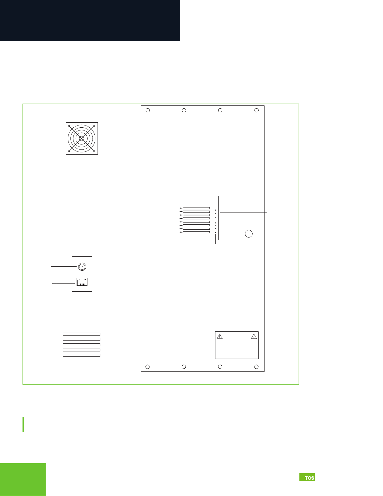
Exterior views
Cloud Connectivity Ethernet Port: Connect an Ethernet cable to the Ethernet port on the side of the QWL4.1 . Connect the
other end of the cable to your network switch port as determined by your local network administrator or IT department.
NOTE: If using a cellular modem provided by TCS, connect the Ethernet cable to the LAN port on the modem (contact
TCS Technical Support at 800.288.9383, ext. 2 for additional information).
CH|ON|DESCRIPTION
WARNING
LOW VOLTAGE PANEL:
24VAC
50/60 Hz ONLY
1
2
3
4
5
6
7
8
CPUALARMWIRELESS POWER
RESET RX TX
Power
Ethernet
Side View Front View
Indicator
Panel
Mounting
Holes
Reset
Button

89
2800 Laura Lane • Middleton, WI 53562 |800.288.9383 |www.tcsbasys.com Building Automation Systems
89
Installation
Interior view of boards and wiring connections Closeup of Ubiquity Cloud gateway ports
Input Wiring
NOTE: The Local Management Ethernet Port (L) on the side of the Ubiquity Cloud Gateway is used only for local onsite
management of the QWL4.1 device. Optionally, this port can be configured as secondary Internet fail-over port (see
Appendix D: Configuring Local Management Port as a Fail-Over Port on page 40 ).
COM Ports (RS-485 Network): Connect up to two RS-485 Networks to the inputs on Com Port panel or on the Serial Board
adjacent to the Gateway. (see RS-485 Controller Network Wiring & Setup on page 10).
USB Ports 1 – 4: As an option, you can connect up to 64 RS-485 controller networks via the four USB ports on the side of
the Ubiquity Cloud Gateway, by using QD1010 USB-to-RS-485 converters (not included).
USB
CABLE
USB
CABLE
ETHERNET
CABLE
Not Used
Not Used
USB PORT 2
USB PORT 1
USB PORT 4
USB PORT 3
LC ETHERNET 2ETHERNET 1
POWER
(12VDC)
HDMIDP
Not Used
Not Available
Not Used
Management Port
Optional RS-485
Input (TCSBus Only)
Interior View
Digital Inputs
Pulse Meter Inputs
Ubiquity Cloud
Gateway Ports
COM 1 RS-485
Inputs
COM 2 RS-485
Inputs
Analog Inputs
USB PORT 2
USB PORT 1
USB PORT 4
USB PORT 3
LC ETHERNET 2ETHERNET 1
POWER
(12VDC)
HDMIDP

92800 Laura Lane • Middleton, WI 53562 |800.288.9383 |www.tcsbasys.com Building Automation Systems
9
Installation
NOTE: Do not install line voltage devices (120VAC or greater) within this panel.
The QWL4.1 is comprised of the following components:
• Ubiquity Cloud Gatewayr
• SLQ218 Lighting Controller
• SLQ100 Electrical Pulse Meter
These components accept the following inputs:
• SLQ218 Lighting Controller:
⸰Eight dry contact/digital inputs
⸰ Two 0 – 5VDC analog inputs
Closeup of lighting controller inputs
• SLQ100 Electrical Pulse Meter:
⸰Four pulse meter inputs
Closeup of pulse meter inputs
DIGITAL INPUTS
ANALOG INPUTS
Pulse Meter Inputs
Z1 – K/Y1
Z2 – K/Y2
Z3 – K/Y3
Z4 – K/Y4

10 11
2800 Laura Lane • Middleton, WI 53562 |800.288.9383 |www.tcsbasys.com Building Automation Systems
10 11
Installation
• Ubiquity Cloud Site Building Manager:
⸰ Power from a 120VAC @ 60Hz to 12VDC power supply module (included)
Closeup of side view of QWL4.1
RS-485 Controller Network Wiring & Setup
The QWL4.1 can handle as many as 64 connected controllers on each port, including COM and serial ports. All
controllers connected to the network must be programmed with the same communication baud rate as well as a unique
communication address from 0 to 255, excluding 248. The baud rate is programmed onsite locally through the monitor
and keyboard, or through remote access through the network. On controllers with displays, this can be done from the
controller using its keypad and display, by using TCS Insight software, or by calling TCS Technical Support (800.288.9383,
ext. 2). TCS Technical Support can access the QWL4.1 online and change the address of a controller.
Network Wiring
The QWL4.1 has a serial board with two RS-485 ports that will accept Modbus and TCSbus Connections. These are the
recommended ports to use for your controller networks.
Recommended RS-485 port locations on serial board
NOTE: There is an additional RS-485 port on the Lighting Control/Pulse Meter Panel labelled “External RS-485”; however,
that port will only accept TCSbus.
CH|ON|DESCRIPTION
WARNING
LOW VOLTAGE PANEL:
24VAC
50/60 Hz ONLY
1
2
3
4
5
6
7
8
CPUALARMWIRELESS POWER
RESET RX TX
Power
Ethernet
Side View
Front View
Indicator
Panel
Mounting
Holes
Reset
Button
Tabla de contenidos
Otros manuales de Instrumento de medición de TCS


Manuales populares de Instrumento de medición de otras marcas


Endress+Hauser
Endress+Hauser Proline Promag 50 Especificaciones técnicas

Siemens
Siemens SITRANS F Coriolis FCT030 Manual de lista de piezas

KLINGER
KLINGER CMF V Series Manual de usuario

EXFO
EXFO FTB-2 Manual de operación y mantenimiento

Keysight
Keysight M8290A Manual de usuario

ADTEK
ADTEK MW-5 Manual de usuario