SUTO S320 Manual

English
Instruction and operation manual
S 320
2-channel display

Dear Customer,
thank you for choosing our product.
The operating instructions must be read in full and carefully observed
before starting up the device. The manufacturer cannot be held liable
for any damage which occurs as a result of non-observance or non-
compliance with this manual.
Should the device be tampered with in any manner other than a
procedure which is described and specified in the manual, the warranty
is cancelled and the manufacturer is e empt from liability.
The device is destined e clusively for the described application.
SUTO offers no guarantee for the suitability for any other purpose.
SUTO is also not liable for consequential damage resulting from the
delivery, capability or use of this device.
2 S 320

Table of contents
1. Safety instructions.......................................................................4
2. Application.................................................................................6
3. Features.....................................................................................6
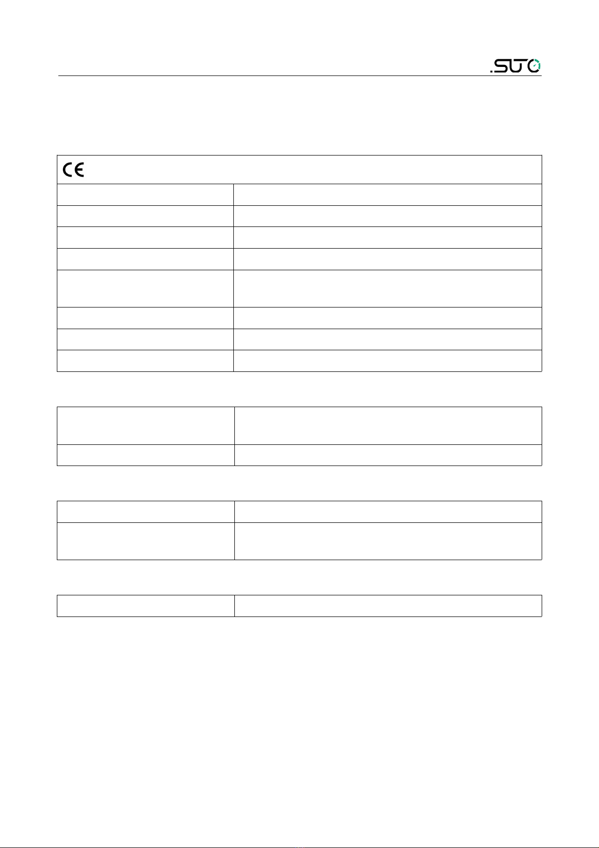
4. Technical Data............................................................................7
4.1 General.................................................................................7
4.2 Electrical Data........................................................................7
4.3 Input-Signals.........................................................................7
4.4 Output-Signals.......................................................................7
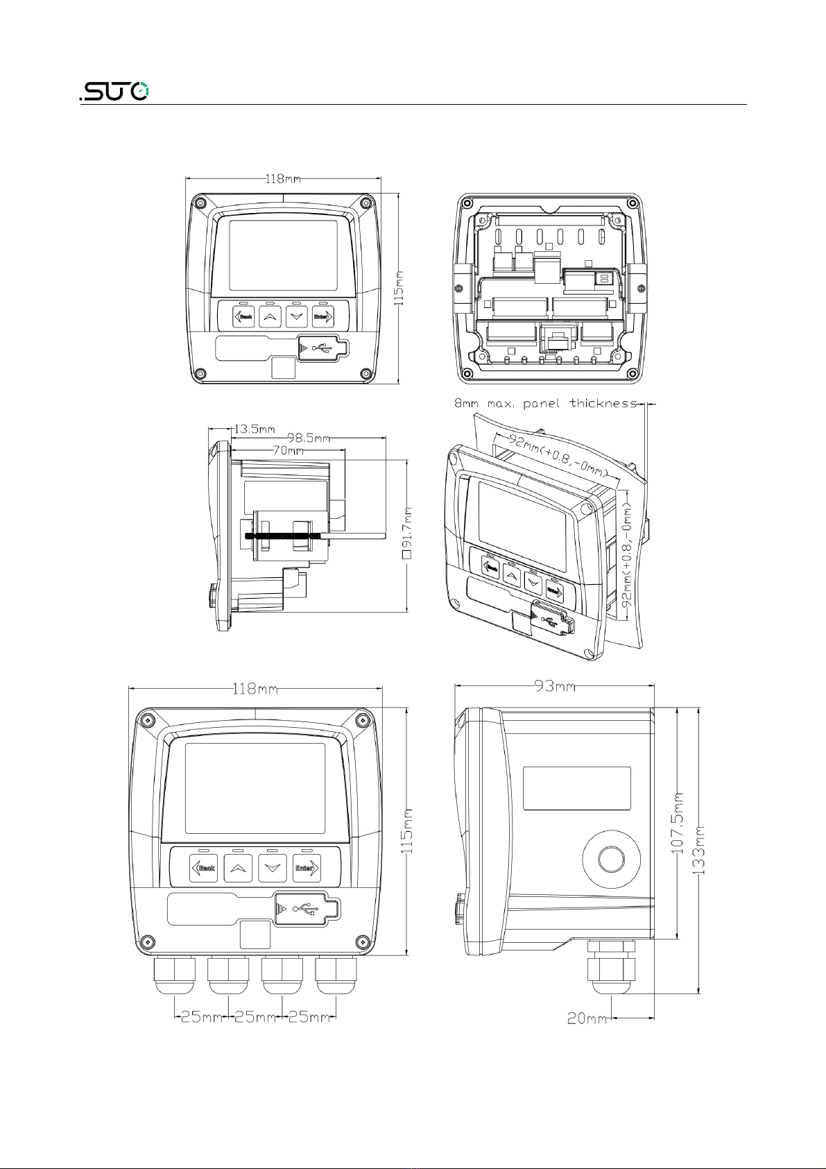
5. Dimensional drawing....................................................................8
6. Installation ................................................................................9
6.1 Installation Requirements........................................................9
6.2 Electrical connection ..............................................................9
6.2.1 AC Power supply and alarm connection (A1640)..................10
6.2.2 DC Power supply and alarm connection (A1641).................10
6.2.3 Signals at back terminals.................................................11
6.2.4 Connection of the following sensors...................................12
6.2.5 Looping the 4... 20 mA of S 215 to a PLC...........................12
7. Configuration ...........................................................................13
8. Operation ................................................................................14
8.1 Description of display icons....................................................14
8.2 Sensor setting......................................................................15
8.3 Alarm setting.......................................................................15
8.4 System status and settings ...................................................15
8.5 Service setting ....................................................................15
9. Signal input .............................................................................15
9.1 Digital input ........................................................................15
9.2 Analog input ........................................................................15
10. Signal outputs.........................................................................16
10.1 Alarm output .....................................................................16
10.2 Interface ...........................................................................16
11. Optional e tra accessories.........................................................16
12. Maintenance............................................................................16
13. Disposal or waste.....................................................................16
14. Warranty................................................................................17
S 320 3

1. Safety instructions
Please check if this instruction manual accords to the
product type.
Please observe all notes and instructions indicated in this
manual. It contains essential information which have to be
observed before and during installation, operation and
maintenance. Therefore this instruction manual has to be read carefully
by the technician as well as by the responsible user / qualified
personnel.
This instruction manual has to be available at the operation site of the
display at any time. In case of any obscurities or questions, regarding
this manual or the product, please contact the manufacturer.
W RNING!
Compressed air!
ny contact with quickly escaping air or bursting
parts of the compressed air system can lead to
serious injuries or even death!
•Only use pressure tight installation material.
•Avoid that persons get hit escaping air or bursting parts of the
instrument.
•The system must be pressureless during maintenance work.
W RNING!
Voltage used for supply!
ny contact with energized parts of the product, may
lead to a electrical shock which can lead to serious
injuries or even death!
•Consider all regulations for electrical installations.
•The system must be disconnected from any power supply during
maintenance work.
•Any electrical work on the system is only allowed by authorized
qualified personal.
4 S 320

1. Safety instructions
W RNING!
Permitted operating parameters!
Observe the permitted operating parameters, any
operation exceeding this parameters can lead to
malfunctions and may lead to damage on the
instrument or the system.
•Do not e ceed the permitted operating parameters.
•Make sure the product is operated in its permitted limitations.
•Do not e ceed or undercut the permitted storage and operation
temperature and pressure.
•The product should be maintained and calibrated frequently, at
least annually.
General safety instructions
•It is not allowed to use the product in e plosive areas.
•Please observe the national regulations before/during installation
and operation.
Remarks
•It is not allowed to disassemble the product.
TTENTION!
Measurement values can be affected by malfunction!
The product must be installed properly and
frequently maintained, otherwise it may lead to
wrong measurement values, which can lead to
wrong results.
Storage and transportation
•Make sure that the transportation temperature of the display is
between -20°C... 60°C.
•For transportation it is recommended to use the packaging which
comes with the display.
•Please make sure that the storage temperature of the display is
between -10°C... 50°C.
S 320 5

1. Safety instructions
•Avoid direct UV and solar radiation during storage.
•For the storage the humidity has to be <90%, no condensation.
2. pplication
The S 320 display can display all relevant parameters (flow, dew point,
pressure, temperature, power consumption, compressor status etc.) in
a compressed air system.
The S 320 display and data logger is not developed to be used in
e plosive areas. For the use in e plosive areas please contact the
manufacturer.
The S 320 display and data logger is mainly used in compressed air
systems in industrial environment.
3. Features
•Graphic display for easy user interface.
•Fle ible power supply: 100 V... 240 VAC / 50... 60 Hz or 18... 30
VDC.
•1 input for flow / dew point sensor.
•1 input for analog sensors: 0... 20 mA, 4... 20 mA, 0... 10 V.
•2 relay outputs for alarm.
•USB interface for configuration with S4C software.
•Wall or panel mountable casing.
•Optional alarm on display.
6 S 320

4. Technical Data
4. Technical Data
4.1 General
Operating temperature 0°C... 50°C
Housing material ABS
Protection class IP65
Dimensions See dimensional drawing on the ne t page
Display Graphic display, 220 140 pi els with back
light
Interface USB to PC
Keyboard 4 keys
Weight 0.52 kg
4.2 Electrical Data
Power supply 100... 240 VAC, 15 VA (option A1640)
18... 30 VDC, 15 VA (option A1641)
Sensor supply 24 V, 10 W
4.3 Input-Signals
Digital input 1 SDI for dew point and flow sensors
Analog input 1 0... 20 mA or 1 4... 20 mA or
1 0... 10 V
4.4 Output-Signals
Alarm output 2 relays, 230 VAC, 3 A
S 320 7

5. Dimensional drawing
8 S 320

6. Installation
6. Installation
Please make sure that all components listed below are included in your
package.
Qty Description Item No.
1 S 320 Panel with ordered options
and if ordered with casing
D500 0320
1 Instruction manual No P/N
6.1 Installation Requirements
The instrument can either be mounted into a panel or if ordered with
the optional wall casing on a wall. Please observe the drawings in
chapter 5 for details. The housing of the S 320 must be fi ed on the
wall using suitable dowels and screws.
6.2 Electrical connection
Terminal block layout at back side
The following diagram is the terminal block layout at S 320 back side.
S 320 9

6. Installation
6.2.1 C Power supply and alarm connection ( 1640)
AC power connection: AC alarm connection:
6.2.2 DC Power supply and alarm connection ( 1641)
DC power connection: DC alarm connection:
10 S 320
Otros manuales para S320
1
Tabla de contenidos
Otros manuales de Registrador de datos de SUTO


