Survision Micropak 3 Manual

LPR Camera Installation &
Settings Manual

This manual is applicable to:
Nanopak: Version 3 and higher
Micropak: Version 3 and higher
Visipak: Version 4 and higher
The SURVISION cameras facilitate a large number of applications
for the road trafc, access control and public safety sectors.
So that the LPR cameras can correctly carry out their required
function, their performance level is crucial. Apart from the settings
adjustment and conguration, the most important factor for
optimal functioning is the camera installation location.
This manual presents the general principles of camera installation,
assembly, aiming and setting adjustment.
It is important that the installation is carried out by a qualied
installer and in a way that is conform to this manual.
The SURVISION teams are at your service to accompany
you throughout your project while taking all your particular
considerations into account.
Introduction
Date of publication: 15/03/2019
Table of Contents

1. Installation location
1.1 - Possible installation locations
1.2 - General installation rules
1.3 - Specic installation rules for car-parks and for normal toll installation when
reading from the front
1.4 - Specic rules for ceiling installation when reading from the front
1.5 - Specic rules for installations in car-parks and normal toll installations
when reading from the rear
2. Assembly
2.1- Assembly and power supply of the NANOPAK Totem
2.1.1 - Assembly procedure with weak electric current
2.1.2 - Assembly procedure with strong electric current
2.1.3 - Installation procedure for totems assembled by SURVISION in factory
2.2 - Assembly of MICROPAK
2.2.1 - Characteristics of the MICROPAK
2.2.2 - Attachment of the support bracket to the wall using the xation kit
with angular displacement provided by SURVISION
2.2.3 - Fixation of support bracket to the ceiling using the xation kit with
anglular displacement provided by SURVISION
2.2.4 - Assembly of AMPHENOL connector
2.2.5 - Diagram of MICROPAK power supply connector
2.3 - Assembly of VISIPAK
2.3.1 - VISIPAK features
2.3.2 - Support bracket installation procedure
2.3.3 - Particular case of SURVISION graduated angle support bracket for
VISIPAK
2.3.4 - Assembly of AMPHENOL connector for VISIPAK
2.3.5 - Assembly of the visor
3. Aiming/Settings adjustment
3.1 - Procedure of adjustment of SURVISION cameras
4. Maintenance
4.1 - Preventative maintenance
4.2 - Firmware update
4.3 - Curative maintenance
4.4 -RMA procedure
Table of Contents

1 - Installation location
4
1.2 - General installation rules
Long plates Small plates*
Sensor Minimum
distance**
Maximum
distance
Max. width
of lane
covered
Minimum
distance
Maximum
distance
Max. width lane
covered
NANOPAK 3 2m/6.56 ft 8m/26.25 ft 4m/13.12 ft 2m/6.56 ft 5m/16.40 ft 2,6m/8.53 ft
MICROPAK 3
12mm 4m/13.12 ft 7.5m/23ft 4m/13.12 ft 3m/9.84 ft 5,5m/18.04 ft 2,6m/8.53 ft
MICROPAK 3
16mm 5m/16.40 ft 10m/ 32.81 ft 4m/13.12 ft 4m/13.12 ft 7,5m/24.61 ft 2,6m/8.53 ft
MICROPAK 3
25mm 8.5m/26.25 ft 15m/49.21 ft 4m/13.12 ft 7m/22.07 ft 10m/32.81 ft 2,6m/8.53 ft
VISIPAK 4 3m/9.84 ft 40m/131.23 ft 7m/22.97 ft 3m/9.84 ft 25m/82.02 ft 4,5m/14.76 ft
* Value for small plates including (not exclusively) the United States, Canada, Mexico, Belgium, Monaco & South America..
** Distance between the camera and the point where we want the plate to be read
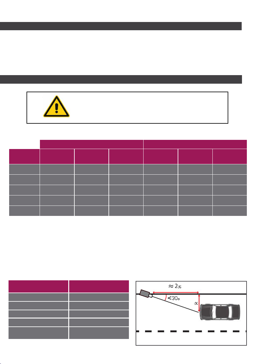
Angle restrictions
The total sum of the vertical angle and the horizontal angle (the angle formed between the
roadside and the camera aiming line) should not exceed 30°.
The camera must point at least slightly vertically downwards to prevent direct illumination
from the sun.
Distance* Height/max posible
side adjustment for 30°
2m/6.56 ft 1m/3.28 ft
5m/16.4 ft 2,5m/8.2 ft
10m/32.81 ft 5m/16.4 ft
15m/49.21 ft 7,5m/24.61 ft
20m/65.62 ft and over 10m/32.81 ft
* Distance between the camera and the point
where we want the plate to be read 5
The eld of vision should be clear of all obstacles:
- Barrier line (horizontal bar)
- Pedestrian crossing in front of camera
- Vehicule crossing in front of camera
Distance restrictions
The SURVISION cameras can read from both front and rear, i.e. :
• The NANOPAK can be installed in a barrier column or in a Totem.
• The MICROPAK and the VISIPAK can be installed on a pole, on a wall,
on a ceiling or on a gantry.
1.1 - Possible installation locations

Where cameras are installed before being connected to the power supply and the
computing network, it is essential that the connectors be protected against water entry.
Installation location rules for maximum performance:
6
• Installation of the camera on the same side as the terminal stand,
• On a curved lane, place the camera to the outside of the curve,
• Where the supporting xture allows it, the lack of horizontality caused by the angles should
be reduced to a minimum,
• The camera view of the vehicle should not be totally or partially concealed by any
environmental element (barrier bar or column, advertising sign, etc…),
• There should be no vehicle or pedestrian passing between the camera and the vehicle
being lmed.
Installation location rules to ensure maximum performance:
See table on page 5 for minimum and maximum distance.
The minimum distance of 3.5m/11.48 ft allows the plate to remain in the image when the
vehicle has come to a stop so that performance is not degraded by other vehicles trying to
pass quickly through behind it.
1.3 - Specic installation rules for car-parks and for normal toll installation
when reading from the front

7
1.4 - Specic rules for ceiling installation when reading from the front
Installation location rules to ensure maximum performance:
1.5 - Specic rules for installations in car-parks and normal toll installations
when reading from the rear
The minimum distance of 7m/22.97 ft ensures that the plate is read before the vehicle arrives
at the terminal, even for the longest vehicles.
The camera must be installed at a horizontal distance “X”, equal to half of H, the
installation height less the height of the barrier bar.
The space given by the distance x ensures that the plate is read before the plate arrives at
the barrier, without the barrier appearing in the image.

8
2 - Assembly

Attention, hot surface
HANDLING PRECAUTIONS
When handling the NANOPAK Totem, please take the required precautions and pay
particular attention to the following diagrams:
Attention, risk of electric shock
Alternating current
The protective earth is a safety measure which makes it possible, in the case of error, to
deliver a dangerous electrical current to the ground.
The protective earth, « PE » measure » is guaranteed by the protective conductor.
The protective earth, « PE » (with green/yellow insulating sheath) is a conductor used as a
measure of protection during an indirect contact to connect metallic elements with:
- other objects;
- foreign conducting elements;
- ground terminals, ground conductors, and active elements which have been earthed.
Warning about a risk due to hot surfaces during the handling, for example, of
machines, tools, etc…
The symbol indicates a dangerous situation which, if the correct behavior is not
adopted, can lead to slight bodily harm and possible material damage.
In order to cause burns to a human being, a hot surface must have a temperature of above
45°C. Warning signs should be present for temperatures above 60°C.
Behavior to adopt:
Such workplaces pose a risk of burning or scalding and those involved with such equipment
must take appropriate care.
Warning of dangerous voltage in the workplace.
Behavior to adopt:
In workplaces associated with a risk of dangerous voltage, personnel must be
qualied (for example, hold electrician qualications and have a knowledge of electronic
engineering) and have the express authorization of the company head.
Non-authorized persons should not have access to these workplaces or open the such-
indicated electrical boxes or cabinets.
Application:
This symbol denotes electrical installations or devices supplied with alternating
current.
Behavior to adopt:
The installations and devices must be provided with an alternating current supply.
Protective earth
Application:
On electrical installations and devices belonging to the electrical
protection class:
“Protective earth”
9

10
2 .1 - Assembly and power supply of the NANOPAK Totem
2 .1.1 - Assembly procedure with weak electric current
5. Reclose the totem to nalise the
installation. Ensure that the screws are
tightenend uniformly.
2. Expose the wires of the brown (positive
and white (Ground) cables. The green
and yellow cables can be connected
to the “dry contact” of the barrier if
necessary.
1. Remove rear part. The NANOPAK is
already installed in the Totem on delivery.
3. If you assemble the Totem directly
on site, the tilt of the camera can be
adjusted by adjusting the 3 screws.
4. The side angle can be adjusted by
pivoting the totem. Adjust the camera
using the conguration procedure on
page 28.
The assembly with weak current corresponds to a 24V power supply located on the outside
of the totem.
Este manual sirve para los siguientes modelos
2
Tabla de contenidos


