Sunway AST Series Manual de usuario

Synway AST Series
TEJ101E
TEJ201E
Digital Trunk Interface Board
Version 1.0
Synway Information Engineering Co., Ltd
www.synway.net

Synway Information Engineering Co., Ltd
Contents
Contents..................................................................................................................... i
Copyright Declaration.............................................................................................. ii
Revision History ...................................................................................................... iii
Chapter 1 Overview.................................................................................................. 1
1.1 Features........................................................................................................... 2
1.2 Operation Principle .......................................................................................... 3
Chapter 2 Installation............................................................................................... 4
2.1 Hardware Structure.......................................................................................... 4
2.2 Interface Identification...................................................................................... 6
2.3 Slot Compatibility ............................................................................................. 6
2.4 System Requirements...................................................................................... 7
2.5 Hardware Installation ....................................................................................... 7
Appendix A Technical Specifications ................................................................... 10
Appendix B Technical/Sales Support ....................................................................11
Synway TEJ101E/TEJ201E Hardware Manual (Version 1.0) Page i

Synway Information Engineering Co., Ltd
Copyright Declaration
This manual is provided by Synway Information Engineering Co., Ltd (hereinafter referred to as
‘Synway’) as the support file for ‘Synway TEJ Series board driver software’. Both the software and
this manual are copyrighted and protected by the laws of the People's Republic of China.
All rights reserved; no part of this manual may be extracted, modified, copied, reproduced or
transmitted in any form or by any means, electronic or mechanical, without prior written permission
from Synway. By using this manual, you agree to the following Software License Agreement.
Synway reserves the right to revise this manual without prior note. Please contact Synway for the
latest version of this manual before placing an order.
Synway has made every effort to ensure the accuracy of this manual but does not guarantee the
absence of errors. Moreover, Synway assumes no responsibility in obtaining permission and
authorization of any third party patent, copyright or product involved in relation to the use of this
manual.
Note: Asterisk and Digium mentioned in this book are registered trademarks of Digium Inc.
Synway TEJ101E/TEJ201E Hardware Manual (Version 1.0) Page ii

Synway Information Engineering Co., Ltd
Revision History
Version Date Comments
Version 1.0 2009-9 Initial publication.
Note: Only major revisions to this manual itself recorded herein.
Synway TEJ101E/TEJ201E Hardware Manual (Version 1.0) Page iii

Synway Information Engineering Co., Ltd
Chapter 1 Overview
The Synway TEJ101E and TEJ201E are digital trunk interface boards which support E1, T1 and
J1 environments. They are in 2U size, half-length, compact in structure and high in integration.
They use high-performance standard PCIe bus, designed especially for various application
systems that require high performance.
The TEJ101E and TEJ201E boards perform echo cancellation by on-board DSPs. The echo
canceller developed by Synway supports up to 128ms for time delay estimation, which ensures
high-quality voice talking without the help of extra modules or devices for echo cancellation. They
are cost-effective. The design of on-board EMC and lightning-proof circuits further guarantee the
security in use.
These boards are completely compatible with Asterisk at the hardware/driver level and support
smooth connection to Asterisk platform. Therefore they have a lot of advanced call features.
Supported Data Modes: Cisco HDLC, HDLC, PPP, Multi-link PPP, Frame Relay.
Supported Voice Modes:
PRI CPE and PRI NET
—NI1
—NI2
—EuroISDN
—4ESS(AT&T)
—5ESS(Lucent)
—DMS100
E&M
—Wink
—Feature Group B
—Feature Group D
FXO and FXS
—Ground Start
—Loop Start
—Loop Start with Disconnect Detect
The TEJ101E and TEJ201E boards connect Asterisk Server with PSTN, Channel Bank or PBX via
T1, E1 or J1 interface to build a specialized telephony network environment. Figure 1-1 and Figure
1-2 below are typical application models with these boards.
Synway TEJ101E/TEJ201E Hardware Manual (Version 1.0) Page 1

Synway Information Engineering Co., Ltd
Figure 1-1 Application Model I: Traditional Telephony System
Note: TEJXXX in Figure 1-1 and Figure 1-2 represent the TEJ101E/TEJ201E boards
Figure 1-2 Application Model II: VoIP Telephony System
1.1 Features
zPCIe Bus Support
Includes PCIe bus; supports PCI Express X1, X4, X8, X16 slots and PNP (plug and play)
feature.
zDMA Read and Write
The use of DMA technique for data reading and writing helps minimize the cost of the host
CPU.
zCompatible with Asterisk
Entirely compatible with Asterisk at the hardware/driver level, with all source codes open.
zRJ48C Jack
The TEJ101E and TEJ201E boards respectively have 1 and 2 RJ48C jacks which can
either connect directly with digital trunks or convert to BNC connectors via a proper adapter,
making connection easy and malfunctions rare.
zEcho Cancellation
The echo canceller developed by Synway uses on-board DSPs to work. It supports up to
Legacy Phones
Legacy
PBX
A
ster
i
s
k
S
erve
r
TEJXXX T1
Internet
R
emote o
ffi
ces
CLEC
A
ster
i
s
k
S
erve
r
TEJXXX T1
IP Phones
LAN
Switch
Synway TEJ101E/TEJ201E Hardware Manual (Version 1.0) Page 2

Synway Information Engineering Co., Ltd
128ms for time delay estimation per channel, really cost-effective. It not only cancels out
the effect of voice playback on DTMF and busy tones detection, but also avoids self-excited
oscillation and howling, and minimizes the possibility of registering wrong DTMF and busy
tones in a conference call, designed especially for VoIP application environments.
zVoice CODEC Support
Supports A-law, μ-law codecs.
zClock Sync Support
The TEJ101E and TEJ201E boards support input and output of CT clock, allowing clock
synchronization with multiple boards.
zEMC & Lightning-proof Circuits Available
1.2 Operation Principle
Mother Board
Figure 1-3 Operation Principle
Inbound PCM Data
Echo
Outbound PCM Data
PCM Interface
Recording Playback
Host Computer Interface (PCIe)
Synway TEJ101E/TEJ201E Hardware Manual (Version 1.0) Page 3

Synway Information Engineering Co., Ltd
Chapter 2 Installation
2.1 Hardware Structure
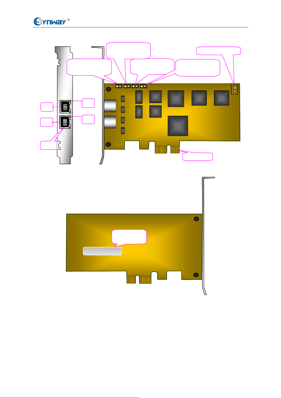
zTEJ101E Board
Figure 2-1 Left and Front Views
Figure 2-2 Rear View
TEJ101E XXXXXX
Board Model
& Serial
OUT1 IN1
Connect to grounding
j
umpers at transmit end
PCM0
JP3
Connect to grounding Clock Sync Interface
j
umpers at receive end
RJ48C
LED1
PCIe Interface
Synway TEJ101E/TEJ201E Hardware Manual (Version 1.0) Page 4
Synway Information Engineering Co., Ltd
zTEJ201E Board
Figure 2-3 Left and Front Views
Figure 2-4 Rear View
Notes:
1) In Figure 2-1 and Figure 2-3 PCM0~PCM1 are 2 transmit/receive interfaces to trunks.
2) LED1 and LED2 are indicators for PCM0 and PCM1. They have three states as listed
below.
○
1On: PCM synchronous; ○
2Flashing: PCM not synchronous; ○
3Off: Port unused
TEJ201E XXXXXX
Board Model
& Serial
OUT1 IN1 OUT2 IN2 JP3
Clock Sync Interface
Connect to grounding
j
umpers at transmit
end of PCM0
Connect to grounding
j
umpers at transmit
end of PCM1
Connect to grounding
j
umpers at receive
end of PCM0
Connect to grounding
j
umpers at receive
end of PCM1
PCIe Interface
PCM0
PCM1
LED1
LED2
RJ48C
Synway TEJ101E/TEJ201E Hardware Manual (Version 1.0) Page 5

Synway Information Engineering Co., Ltd
3) INm and OUTm respectively indicate the grounding jumpers at the receive and transmit
ends, m=1~2. With regard to the configuration of grounding jumpers, refer to Step 1
in Section 2.5 Hardware Installation.
4) JP3 is an interface to the clock sync line.
2.2 Interface Identification
Both TEJ101E and TEJ201E adopt 8-pin RJ48C jack. See Table 2-1 below for the pin layout of
RJ48C.
Pin Note
1 RRing
2 RTip
3 Not used
4 TRing
5 TTip
6 Not used
7 Not used
8 Not used
Pin1
Pin8
Table 2-1 RJ48C
2.3 Slot Compatibility
Make sure it compatible with PCIe slots when using a TEJ101E or TEJ201E board. Users may
choose whichever suitable according to the slot patterns illustrated in Figure 2-5 below.
Slots
3
2
1
0
4
5
6
7
Figure 2-5 PC Slots
Slot Number:
0: AGP Pro slot
1: 64-bit 5.0V PCI slot
Synway TEJ101E/TEJ201E Hardware Manual (Version 1.0) Page 6
Este manual sirve para los siguientes modelos
2
Tabla de contenidos
Manuales populares de Hardware de computadora de otras marcas

EMC2
EMC2 VNX Series Manual del propietario

Panasonic
Panasonic DV0PM20105 Manual de usuario

Mitsubishi Electric
Mitsubishi Electric Q81BD-J61BT11 Manual de usuario

Gigabyte
Gigabyte B660M DS3H AX DDR4 Manual de usuario

Raidon
Raidon iT2300 Manual de usuario

National Instruments
National Instruments PXI-8186 Manual de usuario


