Studio Technologies 5414 Manual de usuario

Copyright © 2020 by Studio Technologies, Inc., all rights reserved
www.studio-tech.com
50600-0620, Issue 4
User Guide
Issue 4, June 2020
This User Guide is applicable for serial numbers
M5414-01151 and later with application firmware 06 and later
and Dante firmware 4.6.0 (UltimoX4 4.2.2.3) and later
Model 5414
Mic/Line Input & Line Output
Dante® Interface

This page intentionally left blank.

Model 5414 User Guide Issue 4, June 2020
Studio Technologies, Inc. Page 3
Model 5414
Mic/Line Input & Line Output
Dante Interface
Table of Contents
Revision History ........................................................... 4
Introduction ................................................................... 5
Installation .................................................................... 10
Configuration ................................................................ 14
Operation ...................................................................... 16
Technical Notes ............................................................ 23
Specifications ............................................................... 26
Appendix A ................................................................... 27

Issue 4, June 2020 Model 5414 User Guide
Page 4 Studio Technologies, Inc.
Model 5414
Mic/Line Input & Line Output
Dante Interface
Revision History
Issue 4, June 2020:
1. Documents deletion of pull-up/pull-down capability.
Issue 3, June 2019:
1. Documents the addition of a DC power input and reference level configuration capability.
Issue 2, August 2017:
1. Documents that the unit now supports the STcontroller software application.
Issue 1, October 2016:
1. Initial release.
Model 5414 User Guide Issue 4, June 2020
Studio Technologies, Inc. Page 5
Model 5414
Mic/Line Input & Line Output
Dante Interface
Introduction
The Model 5414 Mic/Line Input & Line
Output Interface provides a simple-to-use
yet high-performance means of interfacing
analog signals with applications that utilize
Dante® audio-over-Ethernet media network-
ing technology. Four microphone or level-
level sources can be connected to the unit
and then, after conversion to digital, output
by way of a Dante interface. Four signals
arriving by way of Dante can be converted
to analog and then output as balanced line-
level signals. A monitor section allows the
input and output signals to be selectively
observed using meters and a headphone
output.
The Model 5414 is a fully professional
product that offers the audio quality, fea-
tures, and reliability required by 24-hour
on-air and commercial applications. The
four mic/line audio inputs use standard 3-pin
female XLR connectors for easy interfac-
ing with balanced and unbalanced sources.
The input circuitry features adjustable gain,
P48 microphone power, and high-pass filter
functions. Configuration of the inputs can be
made locally by using pushbutton switches
or remotely using the STcontroller applica-
tion. The input audio signals are converted
to 24-bit digital and then transported via the
Dante interface.
Four digital audio signals can be routed to
the Model 5414 via the Dante interface and
are then converted to analog. Four 3-pin
male XLR connectors on the unit’s back
panel provide access to the balanced line-
level outputs. The monitor section provides
the user with the ability to select any input
or output signal, or signal pair, and then
observe their level via LEDs meters and
aurally monitor them by way of a 2-channel
(stereo) headphone output.
Configuration choices allow selection of the
unit’s input and output nominal operating
levels. Independent selections are provided
for the input (analog-to digital) and output
(digital-to-analog) conversion processes.
This capability ensures that the Model 5414
will integrate smoothly into Dante applica-
tions that utilize SMPTE®, EBU, and other
industry-standard nominal levels.
An Ethernet connection is all that’s required
to make the Model 5414 part of a sophisti-
cated networked audio system. Dante audio-
over-Ethernet has found wide acceptance
as an audio “backbone” due to its ease of
use, interoperability, excellent audio qual-
ity, and wide adoption by a large number
of equipment manufacturers. The Model
5414 can serve as an “edge” device for a
Dante network implementation, providing
high-performance input, output, and monitor
resources for applications that need a limited
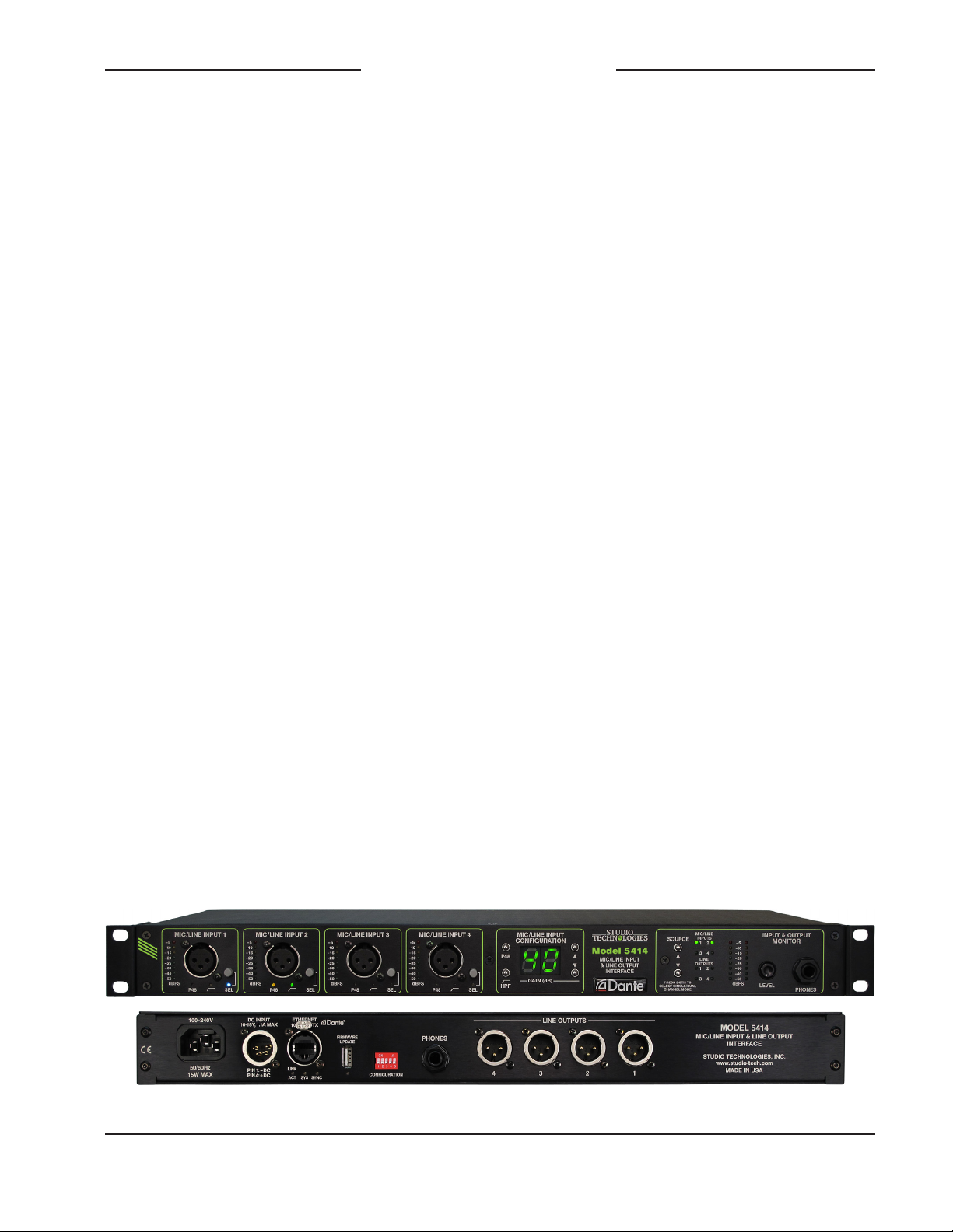
Figure 1. Model 5414 Mic/Line Input & Line Output Dante Interface front and back views

Issue 4, June 2020 Model 5414 User Guide
Page 6 Studio Technologies, Inc.
Model 5414
Mic/Line Input & Line Output
Dante Interface
number of channels. It can also serve as a
general-purpose “tool” to help expand Dante
capabilities to facilities and applications that
were initially implemented to support signals
in the analog domain.
For powering, the unit can be directly con-
nected to an AC mains source. A true
“universal input” design that’s intended for
worldwide use, the input voltage can range
from 100 to 240 volts, 50/60 Hz. A source
of 10 to 18 volts DC can also be connected
to power the Model 5414. If both AC and
DC sources are connected, the AC source
will power the unit while the DC source will
serve as a backup. In this way a battery can
be connected, ready to serve in a standby
capacity.
Standard connectors are used for the
audio input and output, Ethernet, DC input,
and AC mains interconnections. The unit’s
enclosure mounts in one space (1U) of a
standard 19-inch rack enclosure and weighs
less than four pounds (2 Kg).
Dante Audio-over-Ethernet
Digital audio data associated with the Model
5414 is interfaced with a local area network
(LAN) using Dante audio-over-Ethernet
media networking technology. Status LEDs
provide a real-time indication of Dante and
LAN performance. A major benefit of us-
ing Dante to transport professional audio
signals is its compatibility with standard
Ethernet network implementations, including
switches and routers. The Model 5414 sup-
ports digital audio signals with a sampling
rate of 48 kHz and a bit depth of up to 24.
This sampling rate was selected for optimal
support of broadcast, production, industrial,
and commercial applications.
The signals associated with the four mic/line
input channels are converted to digital and
then routed to transmitter (output) channels
on the Dante interface. Four transmitter
(output) channels from one or more associ-
ated Dante-enabled devices can be assigned
to the Model 5414’s receiver (input) channels
using the Dante Controller application. These
input signals are converted into analog and
then sent to the line output circuitry.
The Model 5414 is compatible with the
AES67 interoperability standard. In addition,
the unit is compatible with the Dante Domain
Manager™ (DDM) software application.
Applications
The Model 5414 is a general-purpose mic/
line input, line output, and monitoring device
intended for a variety of audio and audio-
for-picture applications that utilize Dante.
It’s suitable for use in demanding on-air
broadcast and live-event applications that
require both excellent audio performance
and reliable operation. The rack-mounted
unit is appropriate for installation in fixed
locations, serving the needs of systems
associated with stadium, worship, education,
commercial, and government facilities. Its
lightweight enclosure also makes it suitable
for mobile and field uses.
The Model 5414 features an optimized set
of controls and indicators that makes it
simple and intuitive to use. With the unit’s
metering and monitoring resources it’s easy
for operators to obtain optimal performance.
And by providing standard connectors for all
inputs and outputs, along with powering from
AC mains or 10-18 volts DC, setup can be
completed in just a few minutes.

Model 5414 User Guide Issue 4, June 2020
Studio Technologies, Inc. Page 7
Model 5414
Mic/Line Input & Line Output
Dante Interface
Mic/Line Inputs
The Model 5414 provides four analog inputs
that are compatible with microphone and
line-level signals. The mic/line input circuitry
allows the level of the connected sources to
be boosted as required, converted to digital,
and then output to an Ethernet network by
way of Dante. Each mic/line input can be
individually adjusted to meet the require-
ments posed by a wide range of sources.
The choices can be selected either locally
or by way of the STcontroller remote control
software application.
Using two DIP switches, located on the unit’s
back panel, the relationship between the
analog input level and the digital audio out-
put level can be configured. Three choices
are available which allow compatibility with
SMPTE and EBU standards as well as an-
other commonly utilized setting.
The preamplifier gain of each channel can be
selected from among 20 values: 0 dB (line),
10 dB, and 19 through 70 dB in 3-dB steps.
A source of P48 phantom power can be
enabled to power condenser microphones.
In addition, a high-pass filter (HPF) function
can be enabled as required to reduce the
presence of unwanted low-frequency content
typically associated with hum, rumble, or
wind noise.
Compatible signal sources include dynamic,
ribbon, and phantom-powered condenser
(capacitor) microphones. The extended gain
range, up to 70 dB, allows microphones
with low-sensitivity to perform correctly. The
preamplifier gain settings of 0 dB and 10 dB
were specifically included to support con-
nection of balanced and unbalanced line-
level signals that are commonly provided by
professional and semi-professional audio
equipment. Typical nominal levels for these
sources would be +4 dBu and –10 dBV,
respectively. Devices providing these analog
signal sources could include audio con-
soles, wireless microphone receivers, and
broadcast playback equipment.
An 8-segment LED meter is associated with
each of the four mic/line input channels. The
meters are calibrated in dBFS which can as-
sist users in optimizing the preamplifier gain
settings so as to provide the best possible
conversion from the analog to the digital
domain. LEDs display the on/off status of
the P48 and high-pass filter (HPF) func-
tions. For front-panel space efficiency the
four mic/line input channels share a com-
mon configuration section which includes
a 2-digit LED display and four pushbutton
switches. The LED display allows the se-
lected preamplifier gain of the mic/line input
channels to be observed. The buttons allow
rapid selection of the preamplifier gain as
well as controlling the on/off status of the
P48 phantom power and high-pass filter
(HPF) functions.
The mic/line inputs are electronically bal-
anced (differential), capacitor-coupled, and
ESD (static) protected for reliable opera-
tion in a variety of demanding applications.
Extensive filtering minimizes the chance
that radio frequency (RF) energy will cause
interference. The inputs are protected from
damage should a moderate DC voltage be
accidentally connected. The sum of these
characteristics makes the mic/line inputs
suitable for use in studio and mobile facili-
ties as well as field-deployed environments.
The four 3-pin female XLR connectors asso-
ciated with the Model 5414’s mic/line inputs
were specifically located on the front panel.
This can eliminate the need for an external
I/O or “patch” panel, allowing signal sources
and their associated interconnecting cables

Issue 4, June 2020 Model 5414 User Guide
Page 8 Studio Technologies, Inc.
Model 5414
Mic/Line Input & Line Output
Dante Interface
to be rapidly connected as required. Rather
than being “buried” in the back of a rack en-
closure the Model 5414 provides convenient
access to the mic/line input connectors and
their associated configuration buttons, indica-
tors, and displays. “Latchless” 3-pin female
XLR connectors from Neutrik® are utilized to
improve long-term reliability. Using friction,
rather than a mechanical lock, to secure the
mating connector helps to ensure reliable
electrical connections while minimizing the
chance of connector failure.
The audio performance of the Model 5414’s
mic/line inputs is very good. Low-noise,
wide dynamic-range microphone preamplifier
circuits ensure that input audio quality is
preserved. The P48 phantom power source
is extremely low noise, allowing optimal
microphone operation and imparting little
signal degradation. The outputs of the pre-
amplifiers are routed to high-performance
analog-to-digital conversion (ADC) sections
that support a sampling rate of 48 kHz and a
bit depth of 24. A precision voltage-reference
integrated circuit helps the ADC circuitry
perform highly accurate signal conversion.
The audio signals, now in the digital domain,
are connected to the Dante interface section
where they are packetized and prepared for
transport over Ethernet.
Line Outputs
The Model 5414 provides four general-pur-
pose analog line-level output channels. Four
receiver (input) channels associated with
the unit’s Dante interface serve as the audio
sources. The Dante Controller application
software will typically be used to select the
sources which are provided by transmitter
(output) channels on associated equipment.
Using two DIP switches, located on the unit’s
back panel, the relationship between the
digital audio input level and the analog out-
put level can be configured. Three choices
are available which allow compatibility with
SMPTE and EBU standards as well as an-
other commonly utilized setting.
The line outputs are electronically balanced,
capacitor-coupled, and ESD (static) protect-
ed. High-quality components, including the
important digital-to-analog converters, are
used to provide low-distortion, low-noise,
and sonically excellent performance. Robust
circuitry provides protection from damage
should a moderate DC voltage be acciden-
tally connected, something especially useful
in broadcast applications. The line outputs
are compatible with virtually all balanced
and unbalanced loads with an impedance
of 2 k ohms or greater.
Input and Output Monitoring
A flexible yet easy-to-use monitor section
offers the ability to listen to and visually
observe the level of the audio signals that
are associated with the four mic/line input
channels and the four line output channels.
A mode configuration choice allows monitor-
ing of either a single audio channel or
a pair of audio channels. This can be valu-
able when monitoring monaural or stereo
(dual-channel) signals. A 2-channel analog
output supports the connection of a pair
of stereo headphones. For application
flexibility the headphone output can also
be interfaced with inputs on amplified loud-
speakers or a power amplifier associated
with monitor loudspeakers. A rotary control
allows the level of the headphone output to
be adjusted.
For convenience, two ¼-inch 3-conductor
(stereo) phone jacks, one located on the
front panel and one on the back panel, are
provided. The same 2-channel signal is

Model 5414 User Guide Issue 4, June 2020
Studio Technologies, Inc. Page 9
Model 5414
Mic/Line Input & Line Output
Dante Interface
routed to both the front and the back head-
phone output jacks. However, whenever
the front jack is utilized the jack on the back
panel will automatically mute. This mute
function can be useful when the jack on the
back panel is being used to interface with
inputs on loudspeaker systems. Automatic
muting of the loudspeakers will occur when-
ever a pair of headphones is plugged into
the jack on the front panel, a feature espe-
cially important for on-air applications.
Two 8-segment LED meters display the
level of the signal or signals that are select-
ed for monitoring. The meters are calibrated
relative to the digital domain (dBFS), directly
reflecting the signal level in the Dante trans-
mitter (output) and receiver (input) paths.
Simple Installation
The Model 5414 uses standard connectors
to allow fast and convenient interconnec-
tions. 3-conductor male and female XLR
connectors and 3-conductor ¼-inch jacks
are used to interface with the analog input,
analog output, and headphone output audio
signals. The unit connects to a local area
network (LAN) using a standard 100 Mb/s
twisted-pair Ethernet interface. The physical
interconnection is made by way of a Neu-
trik® etherCON RJ45 connector. While
compatible with standard RJ45 plugs and
patch cables, etherCON allows a rugge-
dized and locking interconnection method
that’s suitable for harsh or high-reliability
environments. Three LEDs on the back
panel display the status of the network
connection and Dante interface.
AC mains power can be connected directly
to the Model 5414 by way of a standard
3-pin detachable IEC C13 cord set; no
external power supply is used. Having
a “universal input,” the AC mains power
source can range from 100 to 240 volts,
50/60 Hz. A source of 10 to 18 volts DC can
also be connected to power the Model 5414.
This allows the unit to operate from a vari-
ety of battery and external DC power sup-
ply sources. The power input circuitry was
carefully designed to allow simultaneous
connection of both AC mains and DC power
sources. In this scenario the AC mains
source will power the Model 5414 while
only an extremely small amount of current
will be drawn from the DC source. Upon
loss of AC mains power the DC source will,
without interruption, begin to power the unit.
Far from a simple diode “OR” circuit, this is
a true “hot-swap” type design.
The light-weight aluminum enclosure
mounts in one space (1U) of a standard
19-inch rack enclosure. The rack-mounting
brackets (“ears”), located on the sides of
the Model 5414’s enclosure can be removed
to assistant in achieving special mounting
or installation requirements.
Future Capabilities and
Firmware Updating
The Model 5414 was designed so that
its capabilities can be enhanced in the
future. For example, at the time of the Model
5414’s initial release the ability to remotely
control operating parameters related to
the mic/line input channels is not offered.
But the unit’s internal architecture is such
that adding these capabilities in the future
should be possible.
A USB connector, located on the unit’s
back panel, allows the application firmware
(embedded software) to be updated using
a USB flash drive. Refer to Figure 2 for a
detailed view.

Issue 4, June 2020 Model 5414 User Guide
Page 10 Studio Technologies, Inc.
Model 5414
Mic/Line Input & Line Output
Dante Interface
To implement the Dante interface the Model
5414 uses Audinate’s Ultimo 4-in/4-out
integrated circuit. The firmware in this inte-
grated circuit can be updated via the unit’s
Ethernet connection, helping to ensure that
its capabilities remain up to date.
Installation
In this section the Model 5414 will be in-
stalled and signals interconnected. The
one-rack-space (1U) unit will be mounted
in an equipment rack. An Ethernet data con-
nection will be made using either a standard
RJ45 patch cable or an etherCON protected
RJ45 plug. Audio input and output connec-
tions will be made using 3-pin XLR con-
nectors and ¼-inch 3-conductor jacks. AC
mains power can be connected by means
of a detachable cord set that is compat-
ible with the unit’s 3-pin IEC 320 C14 inlet
connector. Some applications may warrant
connection of a source of 10 to 18 volts DC
which can be made by way of a 4-pin XLR
connector. The DC source can be used to
power the Model 5414 or it can serve as a
backup source for a connected AC mains
source.
System Components
The shipping carton contains a Model 5414
Mic/Line Input & Line Output Interface, user
guide, and AC mains cord suitable for use in
North America and Japan. When installation
will take place in other locations your dealer
or distributor should provide a suitable AC
mains cord.
Locating the Unit
The selected Model 5414 mounting loca-
tion will primarily depend on the unit being
within the 100-meter (325-foot) twisted pair
Ethernet cable limitation. But that can be
overcome by using a fiber-optic interconnec-
tion between the Model 5414-related Ether-
net switch and the other Ethernet switches
in the local-area-network (LAN). Also, as a
device that contains high-gain audio stages,
hum and noise pickup is possible by way of
the chassis and associated cabling. Locat-
ing the unit away from devices that radiate
strong AC fields is recommended.
Mounting
Once a mounting location has been select-
ed installation can begin. The Model 5414
requires one space (1.75 vertical inches
or 1U) in a standard 19-inch (48.3 cm)
equipment rack. Secure the unit into the
equipment rack using four mounting screws,
two per side.
Ethernet Connection
An Ethernet connection that supports
100BASE-TX (100 Mb/s over twisted-pair)
is required for the Model 5414’s Dante au-
dio-over-Ethernet connectivity. A 10BASE-T
connection is not sufficient for Model 5414
operation. A 1000BASE-T (“GigE”) connec-
tion is not supported unless it can automati-
cally “fall back” to 100BASE-TX operation.
Figure 2. Detail of back panel, right side shows
USB connector and status LED
Tabla de contenidos
Manuales populares de Sistema de E/S de otras marcas

WAGO
WAGO 750-344 Manual de usuario

Teknim
Teknim TWM-1887 Manual de instrucciones

Intelligent Appliance
Intelligent Appliance IA-2662-E Manual de usuario

BERGHOF
BERGHOF ECC DIO 16/16 Manual de instrucciones

Advantech
Advantech PCM-27J3AU Manual de instalación y operación

Festo
Festo CP-E08-M12-CL Manual de usuario


