Stratco Solatop Guía de configuración rápida

INTEGRATION
GUIDE
Solatop
TM
INTEGRATION RECOMMENDATIONS
BEFORE YOU START
Carefully read this guide for the layout of the Solatop PV panels. If you do not have all the necessary information contact
Stratco for advice.
POTENTIAL APPLICATIONS
In principle, Solatop PV panels can be installed on any roof section with a minimum slope of 20º and facing North. The
panels can occupy entire roof surfaces or just a portion of the roof surface, meaning there are an almost unlimited
number of potential configurations.
As far as possible, roofs should not lie in the shadow of trees, neighbouring buildings or other objects, otherwise
performance will be correspondingly reduced. It may be necessary to plan for the use of dummy elements for optimum
aesthetic value.

1.0 INTEGRATION INTO AN EXISTING ROOF & WIND LOAD CAPABILITIES
The architect, builder or council is to ensure the existing
or new house/structure is of suitable structural integrity
and complies with all relevant Australian Building codes
and standards.
Roof structure suitability is based on the Solatop PV
panels, Panel Mount Brackets, Mounting Batten, Panel
Support Bracket and Gutter Tray’s having a combined
mass of 25kg per 1m2.
The roof rafters are to have a maximum spacing of
1200mm and to be in sound condition to withstand the
systems mass and environmental loading.
A water proofing membrane is required to be installed
between the Mounting Battens and Rafters. Sarking
membranes and sealing tapes, have to comply with local
requirements and building codes for fire resistance and
stability.
The Solatop PV panel system has been engineered for
residential applications in accordance with AS4055-2006
Wind loads for housing.
The system can withstand loads from wind class, up to
and including, N4 and a maximum wind speed of 50m/s
(permissible). Refer to your local authorities for wind
classification in the specific installation site area.
For more information regarding the suitability of the
house structure to accommodate the Solatop PV panel
system, consult a structural engineer or a building
authority.
It is the builder’s responsibility to ensure that the
existing house roof structure is capable of withstanding
additional loads imposed by the Solatop PV system.
1.1 REQUIREMENTS FOR THE SUB-ROOF AND BATTEN CONSTRUCTION
The Solatop PV panel system requires ventilation between
the overlapped panels, whilst being as water tight as
possible.
A sarking membrane is recommended to be installed on
top of the rafters, making sure the sarking membrane
is lapped from the top, downwards and sealed with the
tape at the lapping joint, to resist water penetration.
The sarking membrane is to be installed across the roof
rafters, loose enough to allow air flow underneath the
Solatop PV panels, but without the possibility of pooling
water.
The sarking membrane will need to exit and attach into
the gutter, without any pooling area’s in front of the
fascia.
The Mounting Batten has been specifically designed
for the Solatop PV panel system. The Mounting Batten
spacing and placement is extremely important to the
finished array - battens must be planar and carefully
levelled if needed.
INTRODUCTION
This guide is intended for architects, builders and
experienced solar installers or individuals who have been
suitably trained and qualified.
Please read this layout guide thoroughly before
commencing the roof lay-out design. Double check
all dimensions, levels and locations when integrating
Solatop PV panels into the roof design.
It is recommended that the persons erecting the structure
have had some previous building experience because
some modifications to the existing house structure may
be required.
Stratco disclaims all liability for damages caused by
inadequate planning or faulty installation.

Figure 1
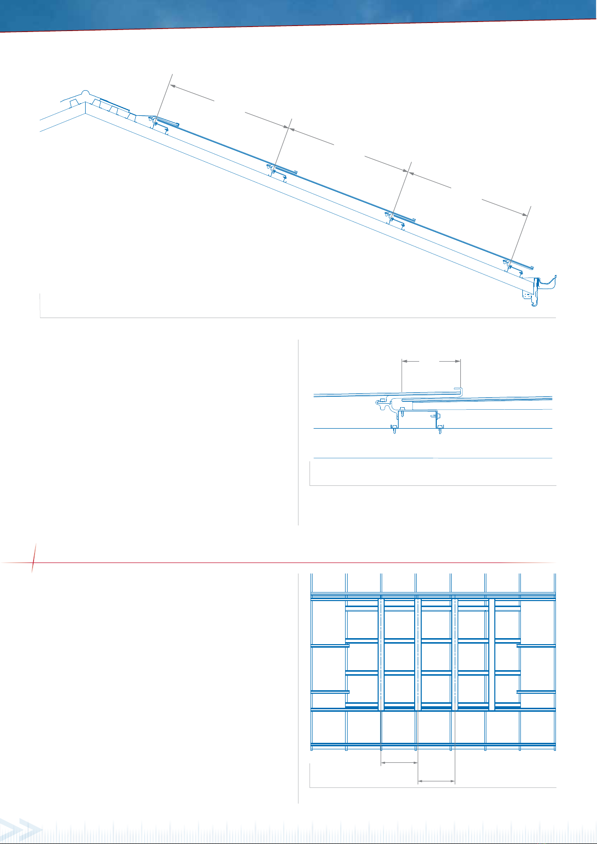
832
270
832
1.1 REQUIREMENTS FOR THE SUB-ROOF AND BATTEN CONSTRUCTION
1.2 TOP MOUNTING BATTEN ARRANGEMENT
When the layout of the Solatop PV panel array starts from
the top of the roof, the first Mounting Batten is installed
270mm from the ridge centre point, as shown in Figure 1.
The batten needs to be parallel to the ridge line, which in
most cases will be the most visible aspect of the roof and
Solatop PV panel system.
The proceeding battens are then installed parallel to
the first batten, with a spacing distance of 832mm. The
battens are to be installed past the end panels and onto
the adjacent rafter.
1.3 BOTTOM MOUNTING BATTEN ARRANGEMENT
When the layout of the Solatop PV panel array starts
from the bottom of the roof, the first Mounting Batten
is installed as close as possible to the gutter, while
still allowing for sarking to exit into the gutter without
ponding, Figure 2.
The batten needs to be parallel to the fascia line, working
back up to the ridge line of the roof.
The proceeding battens are then installed parallel to
the first batten, with a spacing distance of 832mm. The
battens are to be installed past the end panels and onto
the adjacent rafter.

140
958
958
Figure 4
Figure 2
832
832
832
IMPORTANT
As the Mounting Brackets are attached to the Mounting
Battens a standard overlapping distance is created
between the Solatop PV panels. This overlap needs to
be maintained throughout the array of panels, refer to
Figure 3.
The overlap distance will remain the same regardless of
a bottom or top arrangement.
The top Mounting Batten requires a row of Mounting
Brackets to allow a top flashing to be secured and overlap
the top Solatop PV panels.
Figure 3
1.4 GUTTER TRAY ARRANGEMENT
The Outer and Inner Gutter Trays are to be installed with
a centre pitch of 958mm as shown in Figure 4.
The first outer gutter tray needs to be positioned
perpendicular to the battens, leaving enough space
above the top row of panels, to make sure that a flashing
suitably overlaps the gutter tray.
The bottom of the gutter tray will either empty into the
roofs gutter or onto a transition flashing between the
roof cladding and the gutter tray.

Figure 5
1.5 PANEL SUPPORT BRACKETS
The first Panel Support Bracket is to be positioned by
locating the narrow end of the bracket, 16mm past the
edge of the Mount Batten. The Panel Support Brackets
are supplied in a left and right hand configuration.
Figure 5 shows the correct orientation of the bottom
fold which mounts to the Gutter Tray. The Panel Support
Brackets should be mounted as close to the Gutter tray
edge as possible.
2.0 FLASHING RECOMMENDATIONS
Each roofing project has its own particular physical
constraints. Following the design procedures detailed
within this guide will ensure a successful integration of
PV panels with the roof line.
Solatop PV panels can be integrated with the roof
cladding at the top, middle or bottom of a roof section.
They can also be used during the design of new structures
to replace roof cladding as part of the standard build
process.
Solatop PV panels can be incorporated across an entire
roof section. It is necessary to work out the area of roof
available to determine the layout of the Solatop PV panels
and if glass infill panels are required.
The Solatop PV panels and glass infill panels must adhere
to all structural elements of the existing roof including
the strength, watertightness and drainage.
Choosing a system that best suits your design needs is
dependant on the unshaded roof area available.
In Australia fixed Solatop PV panels should be North
facing at a minimum pitch of 20°for optimum electricity
production.
It is the responsibility of the designer/builder to
determine how many solar panels will physically fit in the
chosen roof space. Solatop PV panels can be integrated to
existing roofs, interspersed with standard roof cladding.
DESIGN RULES
Solatop PV panels perform at optimum capacity when
placed in direct sunlight. When designing the new
structure, or installing panels in an existing building,
position the Solatop PV panel array on a North facing
roof section to ensure efficiency year round.
When designing a new building ensure the roof area is
not shaded by trees or other buildings. Shading effects
the potential power production of your solar system.

Top Mounted Solatop Array
Figure 6
PANEL LAYOUT
Solatop PV panels can be placed at the top of a steel
sheet roof. A top row of mount brackets need to be used
to secure and locate the top flashing over the Solatop PV
panels.
Flashings are secured down through the sheet metal
roofing and into the battens.
Solatop PV panels can be placed in the middle of a steel
sheet roof. Sheeting will run under the ridge cap and over
the top flashing giving a neat finish to the roof line.
Solatop PV panels can be placed at the bottom of a steel
sheet roof. The bottom flashing will be turned down into
the gutter aiding water flow.
2.1 PARTIAL INTEGRATION WITH STEEL SHEET ROOFING

Middle Mounted Solatop Array Bottom Mounted Solatop Array
Figure 7
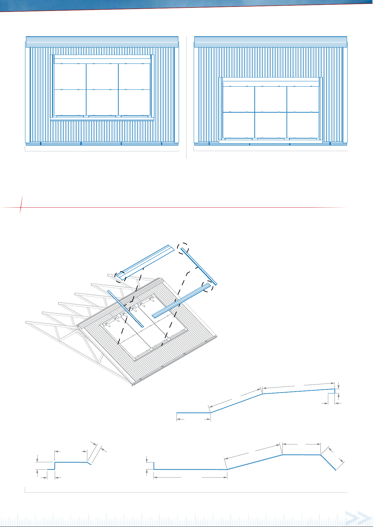
66
Variable
15
15
15
10
10
15
Variable
123
161
A)
B) C)
44
25
Variable
A
B
C
FLASHING RECOMMENDATIONS
Integrating Solatop PV panels into steel sheet roofing will require the use of 4 seperate flashings; top, sides and bottom.
Typical flashing sizes are shown in Figure 7, and should be adjusted accordingly for each roof design.

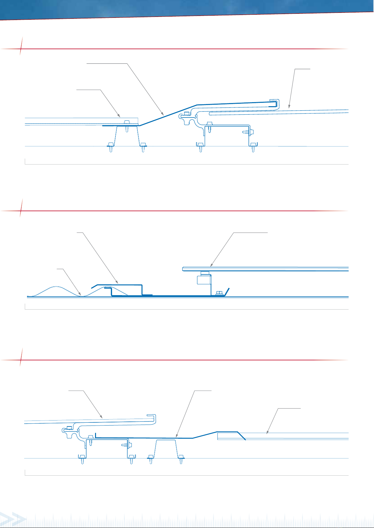
Steel Sheet Roof Integration: Flashing A
TOP FLASHING DETAIL
Top Flashing A
Solatop PV
Panel
Sheet Metal
Roofing
Side Flashing B Solatop PV Panel
Sheet Metal
Roofing
Steel Sheet Roof Integration: Flashing B
Steel Sheet Roof Integration: Flashing C
SIDE FLASHING DETAIL
BOTTOM FLASHING DETAIL
Bottom Flashing CSolatop PV
Panel
Sheet Metal
Roofing

Figure 8
Top Mounted Solatop Array
PANEL LAYOUT
Solatop PV panels can be placed at the top of a tiled
roof. A minimum one row of tiles need to be above the
Solatop PV panels, allowing for grouting and securing of
the ridge cap.
Solatop PV panels can be placed in the middle of a tiled
roof. Tiles sit under the ridge tiles and over the top
flashing, allowing water to fall toward the gutters.
Solatop PV panels can be placed at the bottom of a tiled
roof. The bottom flexible flashing will be turned down
into the gutter aiding water flow.
The bottom flashing comprises a folded metal sheet and
a flexible lead free flashing which forms a water tight
bond when adhered to the roof tiles.
2.2 PARTIAL INTEGRATION WITH TILED ROOFING

A
B
C
A)
B) C)
Variable
12
30
19
20
40
10
10
12
15
161
123
Variable
45
66
10
120
15
15
Variable
Figure 9
Middle Mounted Solatop Array Bottom Mounted Solatop Array
FLASHING RECOMMENDATIONS
Integrating the Solatop PV panels into tiled roofing will
require the use of 4 seperate flashings; top, sides and
bottom. Typical flashing sizes are shown in Figure 9, and
should be adjusted accordingly for each roof design.
The foam insert in side flashings B and D needs to be cut
on site to match the tile profile. The foam insert prevents
water flowing back under the tiles. Flexible flashing C
needs to be formed according to the tile profile.
Tabla de contenidos