Start new
command sequence
Enter to d
1 8 LOG OFF?
Enter d
0
YES
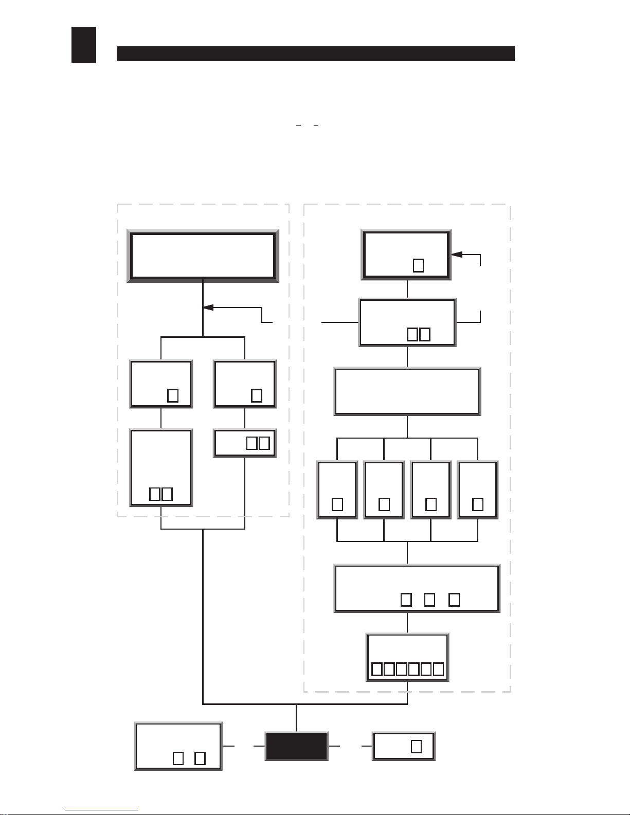
SETTINGTHE ALARM / SECOND DOOR OPTION
Alarm Second Door
Control
To select Alarm or
Second Door option
Enter d
0
Enter d
8
Enter d
1
a) The Remote Exit / Egress Switch
Making a connection (via a suitable momentary contact switch) between connector terminals 10 and 1
(return) will release (or open) the door lock for a pre-set period of time (the door
strike time
).This feature
can be used to provide a
remote exit facility
, allowing personnel to exit from a secure area by pressing
a button located near or adjacent to the door (on the secure side only).
[see sections vii) and viii) for
information about setting the door strike time]
. Please note, in 2 door operation the connection of a
remote egress switch to control the second door is not possible.
b) Alarms
An alarm bell or klaxon can be activated via connector terminals 6 and 7. When the keypad enters an
alarm state (door forced or operator under duress or anti-tamper), these two terminals will provide an
alarm signal (2 Amps max. at 30 Volts DC).The alarm bell or klaxon should be connected as shown in
section iii) - Electrical & Data Connections.
Please note that the alarm bell or klaxon is not powered
from the keypad and so must have an independent power supply.
An alarm signal can be cancelled by keying in any valid
entry code
or the
engineer’s code
. If the cause
of the alarm can be rectified (i.e.The Anti-Tamper switch can be re-closed, or a‘forced door’can be closed),
then keying in a valid ‘Entry Code’ will silence and reset the alarm.
If for any reason the cause of the alarm can not be rectified (e.g.The keypad has been forced away from
the wall, or the door has been damaged and can not be closed), then the alarm can be silenced by keying
in a valid ‘Entry Code’ twice (2 times). When the alarms have been silenced in this way, the keypad must
be isolated from the power for a minimum of 3 seconds to reset the alarm feature.
Note if the alarm function is used to indicate
operator under duress
then the alarm should be
discreet, i.e., situated in a remote location beyond the audible or visual range of an attacker or
intruder.The alarm feature can be used to interface with a centralised alarm system or to trigger
a synthesised or pre-recorded auto dial telephone message to a chosen monitoring station.
Alternatively, terminals (6 and 7) can be used to control a second door.
[Refer to section ix) c) - Controlling a Second Door].
c) Controlling a Second Door
(one keypad controls access
through two doors)
Connector terminals 6 and 7 can be
used as a relay output to control a second door. When the
keypad is used for
second door control
the
Alarms
feature will
be disabled. To configure the keypad for
second door control,
‘log on’,
then enter 8to select
Relay 2 Set Function.
Listen for
the ‘accept bleep’.
Then enter 1to configure the relay for
second door
control
, or enter 0to re-configure the relay as an alarm
output. Listen for the ‘accept bleep’.
(Refer to chart opposite)
d) Door Monitoring (Door 1 only)
In its factory fitted format, the door sensor is disabled.This
is because the hard wire bridge is connected between
terminals 9 and 1 (0V Return and the Door Sensor).
This disables the
door forced alarm
feature. To utilise the door sensor,
remove the hard wire bridge and
connect the door sensor to terminals
1 and 9.
e) Activating the ‘Operator Under
Duress’ Alarm
The
Operator Under Duress Alarm
can be activated at any time by prefixing a valid
entry code
with
the numbers 91. Note: if there is any possibility that this feature
will be used, any visible or audible alarm indicators must be
located out of audible and visual range of any attacker or
intruder.
[Refer to section ix) b) - Alarms].
f) Alarm Output Signal
FEATURE SIGNAL COMMENTS
Duress Relay does not oscilate; stays silent
so as not to alert intruder
Door Forced
Anti Tamper
ix) OTHER FEATURES
6
DES-MAN ISS.3
01234567 time (secs)