Stober EZ Manual de usuario
Operating manual
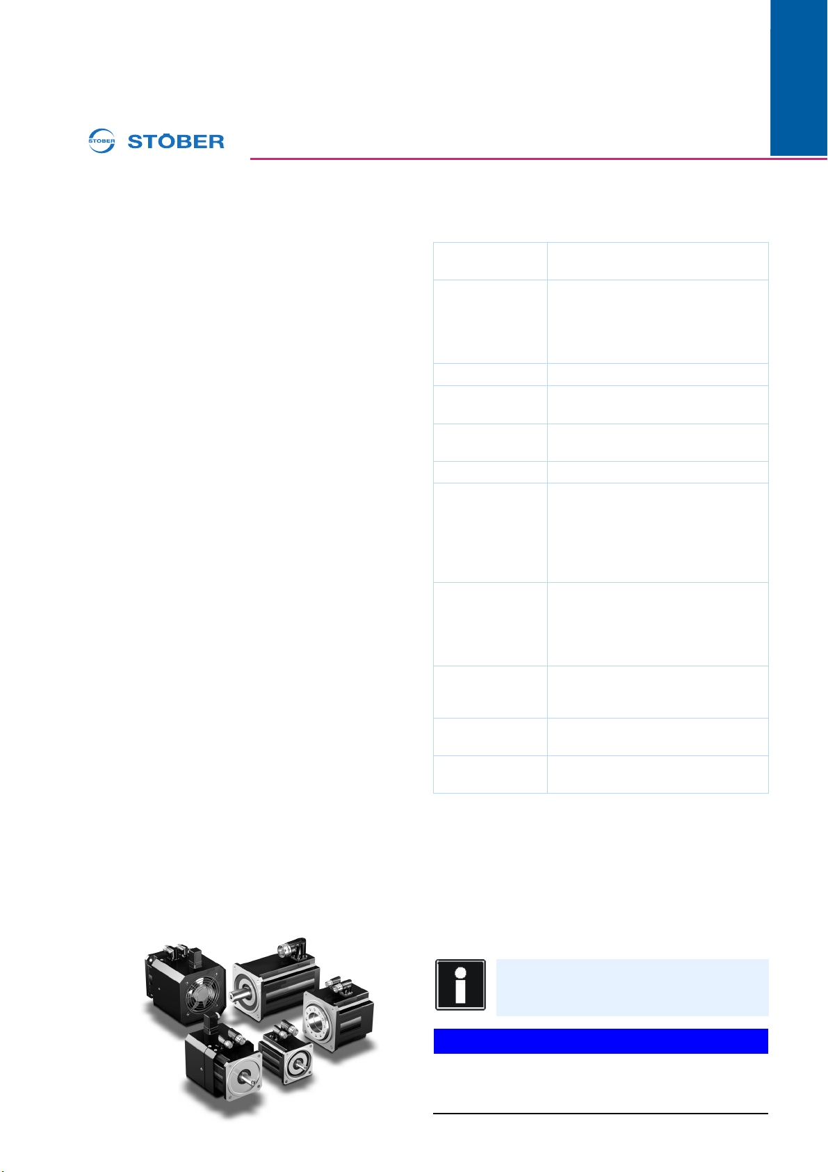
EZ, EZF, EZH, EZHD, EZHP synchronous servo motors / EZS, EZM synchronous servo
motors for screw drive
107/2015
WE KEEP THINGS MOVING
ID 442581_en.03
en
STÖBER ANTRIEBSTECHNIK GmbH & Co. KG
www.stober.com
GERMANY
Tel.: ++49 7231 582-0
These operating instructions contain information about the
transport, installation and commissioning of STOBER EZ,
EZF, EZH, EZHD, EZHP synchronous servo motors and EZS,
EZM synchronous servo motors for screw drive.
For further details, see catalogs SMS-EZ (ID 442212) and
EZS/EZM synchronous servo motors for screw drive (ID
442416).
In the event of any unclear points, we recommend that you
contact STÖBER with the model designation and serial
number, or have the installation and maintenance work
carried out by a STÖBER service partner.
1 Operation in accordance with its
intended use
Synchronous servo motors must be used exclusively for
operating machines and systems together with servo
inverters.
Stay within the limits defined by the technical data.
Do not use synchronous servo motors in potentially explosive
atmospheres.
For reasons of operational safety, motors may only be used
for the single application for which they were projected.
Any overload on the drives is considered unintended use.
The information and instructions in these operating
instructions must be precisely followed to ensure that claims
submitted under the warranty will be honored. If modifications
are made to motors, warranty claims will be rendered void.
Comply with the safety instructions in these operating
instructions and in all supplementary documents for the
synchronous servo motor and other components such as
gear units and servo inverters.
2 Technical data
The technical data for synchronous servo motors, geared
motors and servo inverters that are used is indicated on the
relevant nameplates.
Acceleration / shock load in operation:
The following value for the shock load indicates the value up
to which the motor can be operated without loss of
functionality: 50 m/s² (5 g), 6 ms (maximum value as per DIN
EN 60068-2-27).
Brace the motor connection cable close to the motor so that
vibrations of the cable are not transferred to the motor.
When connecting the motors to drive units such as gear units
or pumps, take into consideration the permissible shock loads
and tilting torques of the units.
NOTICE
Damage to the motor.
XPrevent undue force on the motor such as impact, shock,
pressure or high acceleration.
Designs: IMB5, IMV1, IMV3
(DIN EN 60034-7)
Protection class: EZ, EZF, EZHD: IP56
EZHP: IP56 / IP66 (option)
EZH: IP54
EZS, EZM: IP40
(DIN EN 60529)
Protection class: I
Thermal class: 155 (F) (DIN EN 60034 / VDE 0530)
155 °C, heating ∆T = 100 K
Surrounding
temperature:
-15 °C to +40 °C (with water cooling +5
°C to +40 °C)
Installation altitude: up to 1000 meters above sea level
Cooling: For IC 410 convection cooling;
or optional IC 416 convection cooling
with forced ventilation (DIN EN 60034-
6), see 2.4.1;
or optionally for water cooling in the A-
side motor flange, see 2.4.2
Surface: Black matte as per RAL 9005
Please note! Repainting will change
the thermal properties and therefore
the performance limits of synchronous
servo motors.
Vibration intensity: as per DIN EN 60034-14 degree N
(half wedge balancing for shafts with
key).
Winding: Connection wires: U (U1) - black, V
(V1) - blue, W (W1) - red.
Connection
method:
see motor connection diagrams
Information
If brakes are installed, the holding torques may
be reduced by the shock load!

Operating manual
EZ, EZF, EZH, EZHD, EZHP synchronous servo motors / EZS, EZM synchronous servo
motors for screw drive
2
ID 442581_en.03
WE KEEP THINGS MOVING
07/2015
en
STÖBER ANTRIEBSTECHNIK GmbH & Co. KG
www.stober.com
GERMANY
Tel.: ++49 7231 582-0
2.1 Thermal winding protection
Synchronous servo motors are equipped with a thermistor
(PTC thermistor) in the standard configuration. You can
optionally select the KTY 84-130 as thermal winding
protection.
Make note of the information specified in the SMS-EZ catalog
and in the commissioning instructions for the servo inverter.
CAUTION!
Overheating of the motor!
If the thermal winding protection is not connected, the motor
may overheat as a result.
Possible consequences: destruction of the motor, danger of
fire.
XYou must also take precautions to ensure that no hazard
could occur after the thermal winding protection has
responded and the motor has then cooled off by
unintentional automatic switching on of the motor again!
Always connect to the thermal winding protection. If the
thermal winding protection is not connected, the warranty is
rendered void!
2.1.1 Thermal winding protection PTC
NOTICE
The PTC thermistor is a low-voltage sensor with max. 7.5
VDC connection voltage.
Higher voltages will cause the thermistor and motor winding
to be destroyed.
Always connect to the thermistor. If the drive controller has no
option for PTC evaluation, appropriate triggering devices
must be used for this purpose.
2.1.2 Thermal winding protection KTY
(optional)
Synchronous servo motors can optionally be equipped with a
temperature-dependent KTY 84-130 resistor as a
temperature sensor in a winding. On the KTY the resistance
changes in proportion to the temperature of the winding.
The continuous sensor current icont = 2mA.
NOTICE
When making the KTY connection make certain the
polarity is correct! The installed KTY protects the
synchronous servo motors against overload only to a
limited degree. For this reason the I2t monitoring
parameter should be set to "WARNING".
XAvoid currents >4mA in the KTY circuit, as these could
result in excessively high self-heating of the temperature
sensor and damage to its insulation and to the motor
winding.
CAUTION!
ESD/EGB safety information
This product contains components that can be damaged or
destroyed by electrostatic discharges.
XAlways avoid directly touching the pin contacts with your
fingers!
2.2 Encoder systems
Synchronous servo motors have an encoder system
integrated into the motor for motor commutation and
recording of position. Two-pole resolvers are possible as well
as absolute encoders in various versions.
Note the relevant motor connection diagram and the details
on the motor nameplate. The encoder systems have been set
to the respective servo inverters in the factory.
WARNING!
Changes to the factory settings of encoder systems may
result in uncontrolled startup or vibrating movements of
the motor shaft.
XTherefore the factory settings must not be changed.
CAUTION!
ESD/EGB safety information
This product contains components that can be damaged or
destroyed by electrostatic discharges.
XAlways avoid directly touching the pin contacts with your
fingers!

Operating manual
EZ, EZF, EZH, EZHD, EZHP synchronous servo motors / EZS, EZM synchronous servo
motors for screw drive
307/2015
WE KEEP THINGS MOVING
ID 442581_en.03
en
STÖBER ANTRIEBSTECHNIK GmbH & Co. KG
www.stober.com
GERMANY
Tel.: ++49 7231 582-0
2.3 Holding brake (optional)
A brake with permanent magnet excitation can be installed to
serve as a holding brake.
Power supply: 24 VDC ± 5 % smoothed.
The air gap of the brakes cannot be readjusted.
CAUTION!
An incorrect connection can cause the brake and motor
to be destroyed.
XPlease note when connecting the brake the associated
motor connection plan.
2.3.1 Brakes on gravity-loaded vertical axes
WARNING!
Unintentional lowering or falling of unsecured gravity-
loaded vertical axes can lead to serious personal injuries
or even death!
XThe holding brake of the motor does not provide
adequate safety for person in the hazardous area around
gravity-loaded vertical axes. Therefore the machine
manufacturer must take additional measures to minimize
risks (for example by providing a mechanical
substructure for maintenance work).
Check brake functionality for gravity-loaded vertical axes by
performing a cyclic brake test. To do this load the brake with
1.3 times the load torque. Make certain while doing this that
the suspended load of the vertical axis is already exerting
torque on the motor when it is at a standstill. Take this into
consideration when supplying power to the motor.
2.3.2 Testing holding brake
After making the connection check functionality and measure
the holding torque of the holding brake.
Please note, that the brake types are not defined as working
brakes. Therefore braking from full speed during emergency
stops (power failure or dangerous situations) and braking
while setup mode is active are only permitted within the
defined limits. For further details refer to catalog SMS-EZ.
To ensure that the brakes receive the full braking torque, they
are ground according to a special grinding cycles after final
assembly of the motors. If a brake is not required to exert any
friction over an extended period of time, the friction factor may
change as a result. This can occur due to accumulations of
flash rust or vapors resulting from the high motor
temperature. Slight material distortion may also occur as a
result of major fluctuations in temperature. All of these factors
affect the braking torque.
If the brake does not exhibit the required braking torque, it
must be reground.
To do this, drive the motor as well at max. 20 rpm. Release
and close the brake once per second so that the motor is
required to work against the closed brake for about 0.7
seconds. After about 20 cycles perform the process in the
reverse direction of rotation. In some circumstances you may
need to perform this process several times until the nominal
holding torque of the brake has been reestablished. If the
braking torque has not been reestablished after the grinding
process is repeated four times, other factors may also be
responsible (for example reaching the wear limit). Options for
automatically integrating a grinding routine, if available, are
described in the documentation for the relevant servo inverter
2.4 Motor cooling
CAUTION!
Overheating of the motor!
Reduced cooling, for example due to accumulation of dirt or
fan failure, will cause the motor to overheat, thereby resulting
in damage and/or destruction of the winding.
XTherefore check the functionality of the external fan
during commissioning and at regular intervals thereafter.
2.4.1 Forced-air cooling (optional)
External ventilation is optional and can also be retrofitted due
to the modular layout. This makes it possible to optimize
drives subsequently. Technical data can be found on the
nameplate and in the SMS-EZ catalog in the Motor section.
2.4.2 Water cooling (optional)
NOTICE
Material damage!
To prevent damage to the synchronous servo motor or your
machine, please observe the following:
XComply with the coolant specifications described in this
chapter.
XThe nominal data for synchronous servo motors with
water cooling refers to water as a coolant. If another
coolant is used, you will have to determine the nominal
data again.
XCoolant with fresh water from the public supply grid with
coolants, lubricants or cutting agents from the machining
process is not permitted.
XIf the temperature of the coolant is lower than the
surrounding temperature, interrupt the supply of coolant
when the motor is stopped for extended times to prevent
condensation water from forming.
Cooling circuit specification
Information
The brake must only be tested at a motor speed
of max. 20 rpm!
Feature Description
Coolant Water
Temperature at
inlet
+5 °C to +40 °C (max. 5 K below the
surrounding temperature)
Cooling circuit Closed, with recooling unit
Cleanliness Clear, with no suspended matter or dirt
(use particle filter ≤100 μm if necessary)
pH value 6.5 – 7.5
Hardness 1.43 – 2.5 mmol/l

Operating manual
EZ, EZF, EZH, EZHD, EZHP synchronous servo motors / EZS, EZM synchronous servo
motors for screw drive
4
ID 442581_en.03
WE KEEP THINGS MOVING
07/2015
en
STÖBER ANTRIEBSTECHNIK GmbH & Co. KG
www.stober.com
GERMANY
Tel.: ++49 7231 582-0
3 Safety information
Also follow the instructions in the operating manuals as well
as applicable national, local and system-specific
requirements.
WARNING!
- Danger of electrical shock if unpainted parts conducting
voltage are touched.
- Moving and rotating parts can cause injuries
- Touching the gear unit and motor housing may cause
burns (surface temperatures of over 100°C are possible)
XThe machine manufacturer must provide suitable
protective measures. The connector or terminal box
cover of the motor must remain closed during operation.
All work on the drive must only be performed when no
current is present.
WARNING!
Incorrect operation, improper use, insufficient maintenance or
unauthorized removal of required covers can result in severe
injuries or material damage!
3.1 Personnel requirements
All work on the electrical equipment of the drive units must be
performed by qualified electricians. Installation, maintenance
and repairs of mechanical parts must be performed by fitters,
industrial mechanics or persons with comparable
qualifications.
3.2 In the event of disruptions
NOTICE
Changes compared to normal operation indicate that the
function has been impaired. This includes:
- Higher power consumption, temperatures or vibrations
- unusual noises or odors
- Leaks on the gear unit
- Monitoring devices responding
XIf any of these occur shut down the machine as quickly as
possible and notify the responsible qualified specialist
without delay.
NOTICE
The heat produced while a motor is in operation must be
dissipated into the surrounding air as efficiently as
possible.
Reduced heat dissipation is frequently the reason why
temperature monitoring devices respond.
Accumulations of dirt reduce the performance of the
motor.
XTherefore remove dirt that has settled on the surface of
the motor regularly.
3.3 Safety during installation and
maintenance
NOTICE
Damage to the motor.
XPrevent undue force on the motor such as impact, shock,
pressure or high acceleration.
WARNING!
Risk of injury due to moving parts.
XThe machine manufacturer must provide suitable
protective measures for personnel who must work in the
travel range of a motor within a system or machine,
especially under raised loads.
3.4 Safe function and EMC of the drive
system
The drive controller, cable and motor must be matched to
each other. Each product has specific electrical properties in
and of itself that may affect other products. Unsuitable
matches can therefore result in impermissibly high voltage
peaks on the motor or drive controller, which could destroy
the motor and cause malfunctions in the system. Legal
requirements for EMC (electromagnetic compatibility) must
also be observed.
STÖBER offers a product line of matching cables to ensure
this with suitable shielding technology and cable layout for the
power connection and the various encoder systems.
Using other connection cables and drive controllers may
result in voiding of any claims made under the warranty.
Salinity NaCl < 100 ppm, demineralized
Anticorrosive Maximum percentage 25 %,
neutral relative to AlCuMgPb F38, GG-
220HB
Operating
pressure
≤3.5 bar (provide a pressure relief valve in
the supply line)
Flow rate EZ4 – EZ5: 6 l/min ( 4.5 l/min)
EZ7 – EZ8: 7.5 l/min ( 5.0 l/min)
Feature Description

Operating manual
EZ, EZF, EZH, EZHD, EZHP synchronous servo motors / EZS, EZM synchronous servo
motors for screw drive
507/2015
WE KEEP THINGS MOVING
ID 442581_en.03
en
STÖBER ANTRIEBSTECHNIK GmbH & Co. KG
www.stober.com
GERMANY
Tel.: ++49 7231 582-0
3.5 EZF, EZH, EZHD, EZHP synchronous
servo motors
NOTICE
The hollow shaft of the motors moves in relation to the
supply elements passing though during operation.
XThe supply elements must be protected so they do not
scrape against the hollow shaft.
CAUTION!
The hollow shaft can heat up to 100°C in operation.
XObserve the temperature for the supply elements that
pass through.
3.6 Servo spindle motors EZS/EZM
NOTICE
Destruction of the spindle system!
Removing the spindle shaft from the spindle nut will cause the
system to be destroyed and will void the warranty.
XNever remove the spindle shaft from the spindle nut!
WARNING!
Risk of injury due to moving parts!
Make certain before commissioning that
Xthe spindle shaft and motor are installed in the machine
before you place the drive in operation.
Xno persons will be endangered by the axial movement of
the spindle shaft or slide.
Xno one touches the spindle shaft by coming in physical
contact with it.
WARNING!
Crushing due to contact with the spindle shaft!
Turning the spindle shaft manually with your hand can lead to
crushing injuries.
XNever turn the spindle shaft manually.
CAUTION!
When EZM synchronous servo motors for screw drives
are in operation the spindle shaft moves axially in
reference to the motor.
XFix the spindle shaft in place and install it in the machine.
XScrew the motor together with the machine or moving
slide.
XMake certain there are no objects in the axial movement
range of the slide or spindle shaft.
4 Transport, storage and
preservation
The motors must not be exposed to acceleration levels or
working times of more than 300 m/s² (30 g) as an individual
shock load during transport as per EN 60 068-2-27. The
values for operation apply to long-term shock loads.
When transporting the motors make certain not to damage
the shafts and bearings with impacts.
The motors may only be stored in enclosed, dry rooms.
Storage in open air areas with a roof is only permitted for brief
periods. Protect the motors from all damaging environmental
effects and mechanical damage.
If you will be storing or transporting the system in which a
synchronous servo motor with water cooling is installed below
+3 °C, drain the water completely out of the cooling circuit in
advance.
Avoid extreme temperature fluctuations with high relative
humidity when the motors are being stored temporarily to
prevent formation of water from condensation. If long-term
storage is planned, protect the bare parts of the motor against
corrosion. Before placing a motor in operation again, have the
winding checked for its insulation resistance by an electrical
specialist.
Do not use the fan cover for transport or storage of the
motors. For transport, use the eyebolts on the motors,
together with suitable slings.
Eyebolts are provided only for lifting the motor without
additional attachments. When you remove the eyebolts after
installation, the threaded holes must be permanently closed
corresponding to the protection type of the motors.

Operating manual
EZ, EZF, EZH, EZHD, EZHP synchronous servo motors / EZS, EZM synchronous servo
motors for screw drive
6
ID 442581_en.03
WE KEEP THINGS MOVING
07/2015
en
STÖBER ANTRIEBSTECHNIK GmbH & Co. KG
www.stober.com
GERMANY
Tel.: ++49 7231 582-0
5 Mounting
Completely remove all corrosion protection on the shaft ends
prior to installation.
NOTICE
The lip seals of the shaft seal rings can be damaged by
the use of solvents.
XWhen removing the corrosion protection, make sure that
the lip seals of the shaft seal rings do not come into
contact with solvents.
Tab. 5-1: Assembly information for clamping units
6 Commissioning
Electrical connections provided by the customer must comply
with applicable regulations.
Note:
The electrical connection diagram and safety regulations are
with the delivery documents of the motor. Comply exactly with
the information and safety regulations therein.
WARNING!
Danger of injury from moving parts.
Before commissioning the drive unit, ensure that...
Xno one will be endangered by startup of the machine.
Xall protective guards and safety equipment have been
properly installed, also for a test run!
Xthe drive unit is not blocked.
Xthe brakes have been bled.
Xthe direction of rotation is correct.
Xcomponents mounted on the power take-off end are
sufficiently secured against centrifugal force (e.g. fitting
keys, coupling elements, etc.)
7 Maintenance
7.1 Servo spindle motors EZS/EZM
Axial angular ball bearings are installed on the A-side in the
EZS and EZM motors that directly absorb the threaded
spindle forces. These axial angular ball bearings are greased
with lithium soap grease GA28 at the factory. Under certain
application conditions, for example after a prolonged
downtime or for high humidity, relubrication may be required.
Mineral-based grease is suitable for relubrication, for
example Arcanol Multitop.
Protect the threaded spindle against dirt.
8 Troubleshooting
In the event of a malfunction of the drive unit, call the
STÖBER service department at 07231 582-1190 (-1191, -
1224, -1225) in order to locate the nearest STÖBER service
partner for further action.
In urgent cases outside of normal business hours, you
can call the STÖBER 24-hour service hotline at 01805
786323 / 01805 STOEBER
9 Spare parts
Include the following when ordering replacement parts:
– item no. of the part according to the replacement parts lis
– model designation according to the rating plate
– serial number according to rating plate
You can reach the STÖBER replacement parts service by
phone: 07231 582-1190 (-1191, -1224, -1225), or fax: 07231
582-1010.
Important notice: The replacement parts lists are not
assembly instructions! They are not binding for assembly of
the gear unit. Use only original replacement parts from
Stöber. Otherwise we will provide no guarantee and will
assume no liability for resulting damages!
10 Disposal
This product contains recyclable materials. Observe local
applicable regulations for disposal.
Mount the threaded spindle on the EZS motor:
1. Degrease the threaded spindle in the area where it
comes into contact with the clamping unit.
2. Insert the threaded spindle through the clamping set in
the hole of the motor shaft.
3. The wrench size and the tightening torque that
corresponds to the size of your EZS motor can be found
in the table Tab. 5-1:
4. Tighten the hexagonal screws of the clamping unit
successively in several tightening sequences (approx. 1/
4 revolution per sequence) properly with a torque
wrench until all of them are tightened to the prescribed
tightening torque. Make sure that both spring washers lie
parallel to each other (maximum permitted deviation 0.2
mm).
EZS5 EZS7
Thread M5 M6
Strength class 8.8 10.9
Wrench size [mm] 8 10
Tightening torque [Nm] 5 12
Este manual sirve para los siguientes modelos
6
Tabla de contenidos
Otros manuales de Servoaccionamiento de Stober


Manuales populares de Servoaccionamiento de otras marcas

Mitsubishi Electric
Mitsubishi Electric MELSERVO-J5 MR-J5-G Series Manual de usuario

Robotis
Robotis XH430-W350-T Manual de usuario

NTI AG
NTI AG LinMot C1250 Series Manual de usuario

Welcon
Welcon WE2A D048 Series Manual de usuario

Parallax
Parallax 900-00005 Manual de usuario

Festo
Festo TP 1410 Manual de usuario


