Stevens 93950A Manual de usuario

Stevens Cell-Net
CDMA & GSM M2M
3G Data Modem
Product Manual
Stevens Part #93950A (GSM)
Stevens Part #93950B (Verizon)
updated: July 2015

Page|2
Contents
2. Technical Specifications...................................................................................................................4
2.1 Features............................................................................................................................................4
2.2 LED Indicators..................................................................................................................................5
2.3 Comm Port Pin-out..........................................................................................................................5
3.0 Cell-Net-Set Software.....................................................................................................................6
3.1 Cell-Net Setup..................................................................................................................................6
3.2 Connecting to the modem..............................................................................................................6
3.3 Summery Tab while configuring the modem...............................................................................7
3.4 APN Setting – Using GSM Model...............................................................................................11
3.5 Data Transfer Protocol Tab..........................................................................................................12
3.5.1 HTTP Setup.................................................................................................................................13
3.5.2 FTP Setup...................................................................................................................................14
3.6 Transmission Setup Modes Tab..................................................................................................15
3.7 Comm Port Setup..........................................................................................................................17
3.8 Manufacturing Test Tab................................................................................................................18
3.9 Go Online/ Go Offline Button.......................................................................................................18
4.0 Configuration File Management..................................................................................................18
4.1 File Menu........................................................................................................................................19
4.2 Uploading Configuration to Cell-Net Modem.............................................................................19
4.3 Downloading from Cell Modem...................................................................................................19
5.0 Trouble Shooting...........................................................................................................................19
5.1 How do I know if the data is getting to the modem from the device?....................................19
5.2 What if the modem works during the day but not at night?.....................................................19
5.3 What if the software freezes up?.................................................................................................20
5.4 What do I do if there is poor coverage from the cell tower?...................................................20
6.0 Appendix I – LED Behavior Described.......................................................................................21

Page|3
1. Product Overview
The Stevens Cell-Net is a cellular data modem that operates over cellular data networks,
allowing the transmission of data from any field location that is within the cellular service area.
The Cell-Net CDMA modem includes features for low power operations and data redundancy.
Communication can be made via ether HTTP or FTP protocols as well as IP:Port, allowing data
to be uploaded directly to a web service such as “Stevens Connect” for display, or sent to a
server with FTP access for storage and future analysis, or for direct M2M data connections. The
Cell-Net modem has advanced buffering capabilities allowing for data packets to be queued
ensuring reliability during periods of high cellular data traffic over network towers. Advanced
low-power modes allow Cell-Net to idle for use with low-power solar systems. Transmissions
can be scheduled to occur at set intervals or be event driven, allowing the modem to remain in a
low-power state longer to maximize battery life. Cell-Net features a user-selectable header,
which can include RSSI (receive signal strength Indicator), battery voltage, time, date, latitude,
and longitude information with every data transmission.
Applications include;
•Water resource management
• Soil monitoring
• Golf course / sports turf
• Aquaculture/Agriculture
• Mining
• Tanks
• Bioremediation
• Tidal and port systems
• Environmental and climate monitoring
• Any RS232 to Cellular M2M communication
For additional information about the Stevens Cell-Net, please visit the www.stevenswater.com
or call Stevens at (800) 452-5272.

Page|4
2. Technical Specifications
2.1 Features
LED Indicators
(See appendix for LED behavior definition)
Power: indicates power to the unit
GPS: indicates a GPS location fix
Cell: indicates state of its connection to
the tower.
BIST: Built-In Self-Test
Power Input Voltage
10 to 18 Volts DC
Current Consumption
TX: 300 mA
RX: 150 mA
Idle: <2 mA
TX Output Power
24.3 dBm (270 mWatts)
Ports
RS-232 for M2M communication
USB A for connection to computer for
configuration
SMA connection for cellular antenna
SMA connection for GPS antenna
Unit Weight (without antenna)
10.78 ounces
305.6 g
Dimensions (H x L x W)
1 3/8 x 5 1/8 x 3 ¾ inches
3.5 x 13 x 9.7 cm
FCC ID
RI7DE910-DUAL
RI7HE910
Each Cell-Net includes power cable with flying leads, dipole dual band cellular 800/1900 MHz
antenna, and a USB cable for configuration.
Items sold separately
Part Number Item
93688 Cable, Comms, Universal
DB9 Female
93942-009 SMA to SMA Bulkhead
connector for GPS antenna.
93744 Cable, RS232, black, 3 ft.
93777 Antenna, ruggedized,
900Mhz, 3DB, whip with N
Female
92824-002 Cable Assy, cell modem to
bulkhead, N to SMA, 2 ft.
51108 GPS Antenna, with 5 meters
cable SMA connector.
92845-010 LMR400, N-to-N, Antenna
Cable length per 10 feet
93772 Antenna, 900 Mhz, 9DB, Yagi
with N Connector
93950-108 Antenna, Wide-Band Yagi,
9dB, with N Connector

Page|5
2.2 LED Indicators
The power LED blinks continuously if the modem is powered. The GPS LED stays on while it is
getting a GPS fix goes off once it gets its fix. The Cell LED will flash red while it is in contact with
the tower. The BIST (Built-In Self-Test) LED indicates if there is a problem after a power-on self-
test sequence. Please refer to appendix A for a detailed explanation of LED behavior.
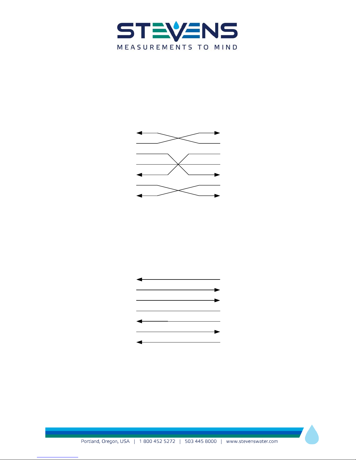
2.3 Comm Port Pin-out
RxD—2
TxD—3
DTR—4
GND—5
DSR—6
RTS—7
CTS—8
Host System—DTE
RxD—2
TxD—3
DTR—4
GND—5
DSR—6
RTS—7
CTS—8
Cell-Net—DTE
Null Modem Connection
for Cell-Net Setup
Cell-Net is a DTE, Use this pinout configuration when connecting the serial comm port to
another DTE such as a computer. Note that you will need a null modem cable or a null modem
with a straight through cable to connect to a computer through the serial port.
TxD—2
RxD—3
DSR—4
GND—5
DTR—6
CTS—7
RTS—8
RS232 Equipment—DCE
RxD—2
TxD—3
DTR—4
GND—5
DSR—6
RTS—7
CTS—8
Cell-Net—DTE
Straight Cable Connection
for Cell-Net Use
Cell-Net can be connected to a DCE such as a data logger or any other RS232 device using a
straight through cable.

Page|6
3.0 Cell-Net-Set Software
Cell-Net can be configured with Cell-Net-Set software. Cell-Net-Set Software can be loaded
from the CD that accompanied the shipment of this product.
3.1 Cell-Net Setup
Once Cell-Net-Set Software is installed on the computer, and the Cell-Net modem is properly
powered with a 12 volt DC source, connect a USB cable between the modem and the computer.
3.2 Connecting to the modem
When the software is first opened, the “Go Online/Go Offline” Button (see section 4) will say that
it is not connected near the top. In the summery tab, click the down arrow in the connection box.
If the modem is connected through the USB, the MEID or IMEI of the connected modem will
appear. In this example, the IMEI number is 354660047225845, but will be different for every
modem.
Note: The Connection field will be “greyed out” until USB enumeration has taken place. After
which, the pull-down menu will be available. This can take up to 1 minute after power up.

Page|7
3.3 Summery Tab while configuring the modem
By clicking on the MEID or IMEI number in the connection box, the modem is connected. The
term “Idle” will appear at the top of the window.
The file menu in the top left hand Conner of the window will allow the user to save a
configuration. The user may also load a configuration that is saved to the hard drive location on
the local machine. This will allow users to conveniently put the same configuration on multiple
modems. The Help menu in the software contains a subset of the information that is in this
manual.
“GPS Fix Info:”
If there is no GPS Fix, then this field will say “Invalid Fix”. If the modem has a GPS Fix, the
longitude and latitude in WGS84 decimal degrees is displayed. The modem will not get a GPS
fix if it does not have a GPS antenna. However, the modem will still function normally without
the GPS clock and position fixes. The Cell-Net time will default to cellular network time.
“Get Current GPS” Button
Pressing the GPS Button will update the GPS Fix Info field, as long as a GPS antenna is

Page|8
connected and sufficient time is given to get a GPS fix. 90 seconds is a typical time for this if
there is a clear view of the sky.
“RSSI From the last tower ping”
The RSSI is the received signal strength index between the modem and the cell tower. It is the
log of the received power in Watts. The measurement unit for RSSI is dbm. The RSSI can range
from -51 to -113 dBm.
CDMA GSM
RSSIdBmUnitsQualityRSSIdBmUnitsQuality
-51 dBm or more Excellent -51 dBm or more Excellent
-53 dBm Excellent -53 dBm Excellent
-55 dBm Excellent -55 dBm Excellent
-57 dBm Excellent -57 dBm Excellent
-59 dBm Excellent -59 dBm Excellent
-61 dBm Excellent -61 dBm Excellent
-63 dBm Excellent -63 dBm Excellent
-65 dBm Excellent -65 dBm Good
-67 dBm Excellent -67 dBm Good
-69 dBm Excellent -69 dBm Good
-71 dBm Good -71 dBm Good
-73 dBm Good -73 dBm Good
-75 dBm Good -75 dBm Good
-77 dBm Good -77 dBm OK
-79 dBm Good -79 dBm OK
-81 dBm Good -81 dBm OK
-83 dBm Good -83 dBm OK
-85 dBm Good -85 dBm Marginal
-87 dBm Good -87 dBm Marginal
-89 dBm OK -89 dBm Marginal
-91 dBm OK -91 dBm Marginal
-93 dBm OK -93 dBm Marginal
-95 dBm OK -95 dBm Marginal
-97 dBm OK -97 dBm BAD
-99 dBm Marginal -99 dBm BAD
-101 dBm Marginal -101 dBm BAD
-103 dBm Marginal -103 dBm BAD
-105 dBm Marginal -105 dBm BAD
-107 dBm BAD -107 dBm BAD
-109 dBm BAD -109 dBm BAD
-111 dBm BAD -111 dBm BAD
-113 dBm BAD -113 dBm BAD
??? not detected very BAD ??? not detected very BAD

Page|9
The chart above can be used to interpret the RSSI for trouble shooting purposes.
If the RSSI becomes marginal or bad in the chart, it may indicate a problem with the antenna. If
the RSSI is marginal or bad, check to see if the antenna screw connection is tight. A low RSSI
can also indicate a bad location for the Cell-Net in relation to the nearest cellular tower. An
antenna with higher gain might be necessary. See the table in section 2.1 for higher gain
antenna options.
“Get Current RSSI” Button
This button updates the RSSI information. It is useful for trouble shooting poor cell coverage
areas or antenna issues.
“FW Revision”
This field displays the revision number of the firmware programmed into Cell-Net.
“Battery Voltage (V)”
This field displays the level of the power source the modem is connected to in volts. 12 volts is
typical.
“Current and Date and Time”
This field displays the current date and time on the modem.
“Get Cell-Net Time” Button
This button will update the date and time field above.
“IP Address”
This field shows the IP address of the modem. It may be dynamic or static depending on the
data plan.
“Data Transfer Protocol:”
This field describes the protocol Cell-Net is programmed to use. It will say HTTP, FTP or Both.
Use the Data Transfer protocol tab to change this as described in section 3.5.
“Transmission Mode”
This field will state the relevant transmission mode conditions of the Data Transfer Protocol
programmed into Cell-Net. To edit these modes, use the Transmission Setup Modes tab as
described in section 3.6.
The Serial Port Properties; Baud Rate, Party, Flow Control, Data Bits, Stop Bits, are displayed.
The serial port settings are setup using the Comm Port Setting tab and described in section 3.6.

Page|10
“Clock Sync”
This field shows whether the feature Clock Sync is disabled or enabled for use. It is described in
section 3.7 for the Comm Port Setting tab.
“CTS Wakeup”
This field shows if the modem is using CTS to wake up a logger or device through its RS232
port. It is described in section 3.7 for the Comm Port Setting tab.
“Internal Data Selected for Transmission:”
This field shows the header information the modem is programmed to send, See Transmission
Setup Modes tab in section 3.6.
“Reset” Button
The reset button recycles power on the modem and will perform its BIST (Built-In Self-Test) and
enumerate the USB again just like when the device is first powered.
“Restore to Factory Defaults” Button
This button returns the modem to its factory defaults. The cellular data plan is associated with
the MEID or IMEI number which cannot be changed; therefore hitting the reset button will have
no effect on the cellular data plan.
Este manual sirve para los siguientes modelos
1
Tabla de contenidos
Manuales populares de Módem de otras marcas

US Robotics
US Robotics 3453C Manual de usuario

MaxTech
MaxTech Plug & Play Internal Voice/FAX/Data/SVD... Manual de usuario

Zte
Zte MF823 Manual de usuario

Four-Faith
Four-Faith F1403 Manual de usuario

Sierra Wireless
Sierra Wireless AIRLINK MP595W Manual de usuario

Gemtek
Gemtek WiMAX WIXFBR-103 Manual de usuario