STEIN PROJECT Manual de usuario

NOV 2020
IMPORTANT!
1. When you receive your Project Shower package please check for any freight damage.
2. If damage has occurred advise your supplier within 8 hours.
3. Do not install any faulty product as this will invalidate later claims.
PROJECT SHOWER 2-SIDED FRAMELESS

2
WARRANTY
• This covers faulty product. Check www.stein.co.nz for full details of warranty.
• Any breakage on site will not be covered.
• The installation must conform to the instructions for the warranty to apply.
HEALTH & SAFETY
• Glass is heavy and requires two people to handle in most applications.
• Always stand glass up after unpacking the components and use soft packing when in
contact with hard surfaces. Take care not to strike an edge or corner on a hard surface.
• All glass is toughened and cannot be reworked or drilled.
• Wear protective gloves and eye protection.
• Special care should be taken when drilling walls to avoid hidden pipes or electrical cables.
IMPORTANT PREPARATION STEPS !
1. Solid xing must be provided in the walls behind the wall channels. 30mm centre off
outside of the Acrylic tray.
2. Plumbing ttings in the wall need suitable solid xings.
3. All Plumbing must be completed by a registered plumber and be in place prior to being
lined.
4. The wall lining must be a “Wet Area” grade to meet the Building Code.
5. The oor must be level and at without deection. Walls must be plumb and surfaces at.
6. The Acrylic Tray and Liner comes with its own specic instructions.
7. Tiling Option: Floor and Walls must be waterproofed by a certied applicator and a
producers statement provided to Council authority.
Include a Water Stop at the Shower boundary. This must comply with AS3740 standard.
TOOLS REQUIRED (NOT SUPPLIED)
PROJECT FRAMELESS SHOWER 2-SIDED
WE RECOMMEND A TRADESMAN FAMILIAR WITH THIS TYPE OF INSTALLATION
MATERIALS REQUIRED (NOT SUPPLIED)
• Rags and suitable cleaning materials
• Acrylic Shower - Sika Silaex NG Silicone (from your merchant)
• Tile Shower - Bostik V60 (available from glazing companies)

3
REF DESCRIPTION PART NO. QTY REF DESCRIPTION PART NO. QTY
2 Screws M4x35 PAR1036 8 11 Threshold Waterbar with 3M Tape PAR1217 1
3 Wall Channels PAR1027 2 12 Water Deector PAR1214 1
4 Return Panel 1 13 Floor Channels with 3M Tape PAR1215 2
5 Door Seal PAR1210 1 14 Support Panel PAR1216 1
6 Handle Set PAR1211 1 15 Screws M4x8 PAR1036 8
7 Door Panel 1 16 Screw Cover Caps PAR1036 8
8 Buffer Seal PAR1212 1 17 Hinge Panel 1
9 Glass Clamp PAR1213 3 18 Packer Block Set STE1128 1
10 Hinges STE1009 2
[18]
Before commencing installation, please ensure you have the following components in your
package to complete installation.
ASSEMBLY DIAGRAM

4
DIAGRAM A
2
WALL
CHANNEL
22mm
Minimum to Maximum Table
SHOWER SIZE DOOR SET RETURN PANEL
900 x 900 2 Sided 856mm - 868mm 861mm - 873mm
1000 x 1000 2 Sided 956mm - 968mm 961mm - 973mm
1200 x 900 2 Sided 1156mm - 1168mm 861mm - 873mm
NOTE: All measurements assume the oor is level, the walls are plumb and all surfaces are at. Any
variation must be adjusted for in the measurements provided.
INSTALLATION STEP 1 2-SIDED ACRYLIC
BEFORE YOU START: Decide on the two Door-Set Layout options offered.
OPTION 1: Standard version is outlined in these instructions from page 4 to 9.
OPTION 2: This varies from standard option using vertical seals either side of the door. The door gaps
will be 4mm wider than standard version. Start at the outset if applying this option. Go to
appendage page 10 to get all the details
STEP 1: Wall Channel positioning and attachment
Tile Tray Set-Out: Use the Min to Max
Table to position the glass panels to the tray.
Channel Fixing: Do not penetrate the tiles and
waterproong but bond full width and length of
channels with Bostik V60 Structural Silicone. Leave
a minimum of 36 hours prior to installing shower.
Acrylic Tray Set-Out: Mark position on
acrylic tray and check against the Min to Max Table.
Channel Fixing: Plumb up channels, drill 2mm hole
in liner. Apply 7mm bead of silicone sealer the full
length of channel and fasten with 3.5x4mm screws.
ACRYLIC
TRAY

5
3. Ensure the oor channel positions are marked.
4. Peel off the backing tape under the oor channels and
waterbar and carefully bond these to the tray.
5. Place self-adhesive block as shown in this diagram.
1. Floor channel line is 1mm in from wall channel.
2. Temporally place the return panel oor channel in position, cut waterbar to 605mm to mark out
panel hinge panel oor channel outer point (Diagram B).
INSTALLATION STEP 2 FLOOR CHANNELS
Floor Channel
Waterbar
positioned out
2mm past Hinge
Panel Floor
Channel
DIAGRAM C
Packing to level up glass panels is important step and the initial set-up is based on 2mm packers.
Variation in packing will be needed. Refer to next page for essential detailing including Diagram E.
INSTALLATION STEP 3 LEVELLING OF FIXED GLASS WITHIN FLOOR CHANNELS
Check levels of
Floor Channel
Check levels of
Floor Channel
Initially place
packer across the
top of Channel to
assess levelling
D1
D2
DIAGRAM D
Outer Floor
Channel Points
Door
600mm
Hinge
Gap
Door to
Return
Panel Gap
Self adhesive blocks
3mm
2.5 to 3mm
Waterbar
DIAGRAM B
Channels are cut to length
and stop short of wall
channel. This is required for
the vertical prole on the
back of the glass panel to
t behind.

6
Top of Hinge Panel
is 10mm shorter
at top than bottom
Glass Positioning Indicators
1. Arrow shows top of glass panels.
2. Hinge panel cut-out as Diagram F.
3. All glass proles are 4mm below the
bottom glass edge as Diagram E.
DIAGRAM F
Check you have glass panels up the right way (refer Diagram F). The specications for glass vertical
aluminium prole is 4mm below the glass.
Standard packing under the glass is 2mm but analyse your requirements.
Height Adjustment at wall
To reduce height from 2mm packing also needs trimming the bottom of vertical prole this amount
(Standard past glass is 4mm). Packing above 2mm will make an equal gap under this prole
Height Adjustment adjacent to door
A reduction from 2mm will require the door to be raised to keep 14mm clearance for Seal/Waterbar.
INSTALLATION FIXED GLASS PANEL FITTING DETAILING
Fixed Glass & Floor Channel Layout
Leading Glass Edge
Fixed Glass
Profile
Bottom of Glass Floor Channel
Depth 14.5mm
2mm Standard
Glass Packer
4mm
Profile extends 4mm
below glass edge
DIAGRAM E

7
INSTALLATION STEP 4 FINAL PLACEMENT OF FIXED GLASS PANELS TO CHANNELS
1. Apply silicone along the inside of the oor channel (Diagram G2). Ensure the build is enough to seal
and bond the glass to the inside of channel with a moderate excess. Do not overll.
2. Apply silicone to four positions as shown in Diagram G.
3. Fit the glass in place ensuring it has bottomed to packers. Clean excess silicone.
4. Plumb up glass leading edges and check door gap is 606mm max.
DIAGRAM G
WALL CHANNEL
FLOOR CHANNEL
Apply silicone on the Wall
Channel leading edge both sides.
Apply silicone on the inside
of the Floor Channel on the
leading edge on BOTH sides
G1
Apply silicone bead (G3) the full length
of Floor Channel
G2
Silicone build
detailing
Packer
Silicone bead
on inside of
channel
G3
1. Use a 3.2mm drill bit to establish four even holes within the wall channels (Diagram H).
2. Drill and x to the wall channels with the 8x4x8mm screws provided (Diagram I).
3. Place cover caps over screw heads.
INSTALLATION STEP 5 WALL CHANNEL FIXING
DIAGRAM H
20mm
H1
H2

8
INSTALLATION STEP 6 GLASS TOP SUPPORT PANEL
INSTALLATION STEP 7 DOOR INSTALLATION
Glass Support Panel Fitting
1. Position the three glass clamps as in Diagram I.
2. The clamp on the return glass must be positioned back for door clearance.
3. Ensure these are tight and adjusted to door opening measurement.
1. Fit hinges to the hinge panel glass (17) Diagram J1.
2. Fit handle (6) to door, Diagram J2.
3. Install the door (7) in place and adjust to t.
DIAGRAM I
Check when the door is ush at top that a 7mm gap (Min) is achievable underneath door glass to the
waterbar.
Packer to elevate hinge
(if required)
Fit door seal
DIAGRAM J
J1
J1
J2
J2

9
150
Seal detail for both
wall/corners
INSTALLATION STEP 8 COMPLETION: SEALING OF EXTERNAL JOINTS
1. Silicone seal boundary joints as indicated including detailing of corners.
SCREENS THAT ARE SEALED ON THE INSIDE WILL VOID WARRANTY UNLESS INDICATED OTHERWISE
IN THIS MANUAL.
DIAGRAM K
CONTACT
Freephone: 0800 002 299 Phone: 07 928 9990
10
Variation to standard installation:
If surrounds adjacent to shower enclosure are not designated a ‘”Wet Area”, we have provided
vertical seals for each side of the door (Regulating authorities will dictate requirements in your
region).
This required change must be understood
and applied at the outset.
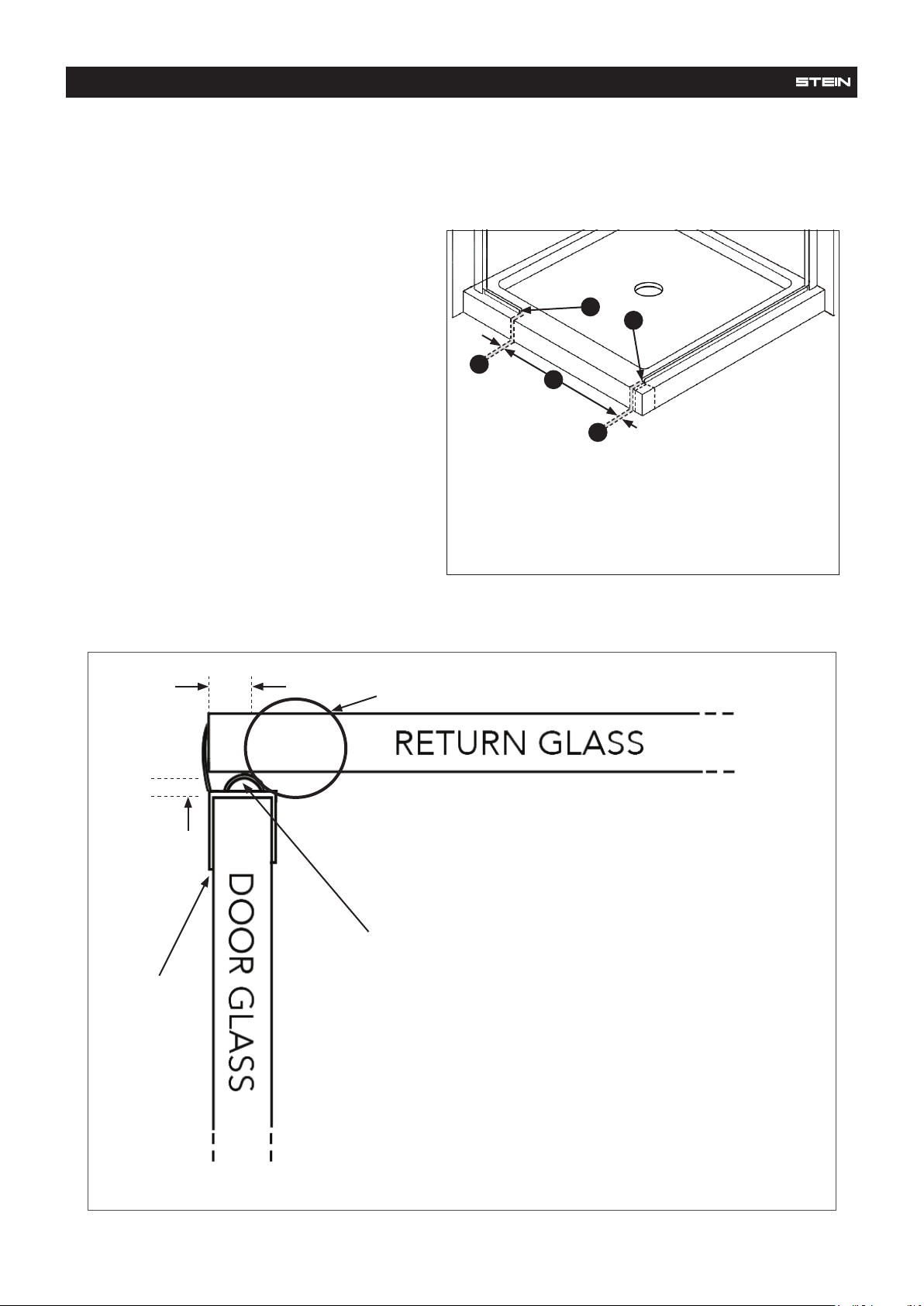
VERTICAL DOOR SEALS APPENDAGE PAGE
4-6MM
REQUIRES FINAL
ADJUSTMENT
6.5MM GAP
VERTICAL SEAL
ADJUST TOP SUPPORT GLASS BRACKET TO ACT AS A DOORSTOP
DIAGRAM 2 DETAILING OF SEAL AND SUPPORT GLASS BRACKET POSITION
A - Hinge Gap: 3.5mm
B - Door: 600mm
C - Door to Return Panel Gap: 6.5mm
D - Outer Floor Channel Points
A
C
B
D
D
DIAGRAM 1
1. Door gaps will be 4mm wider than
Option 1 to allow for the vertical seals.
2. Waterbar must measure 609mm.
• ADJUST THE DOOR SO THE BUFFER
SEAL HAS A LITTLE FRICTION AGAINST
THE RETURN PANEL.
• THIS “SEAL SET-UP” MEANS THE
DOOR OPENS OUT ONLY.
Tabla de contenidos
Otros manuales de Accesorio de baño de STEIN

STEIN
STEIN CURVED ACRYLIC Manual de usuario

STEIN
STEIN GEORGIA Manual de usuario

STEIN
STEIN TURTLE SHELL Manual de usuario

STEIN
STEIN EASYCLEAN WASTE Manual de usuario

STEIN
STEIN Georgia Acrylic Manual de usuario

STEIN
STEIN WINDSOR SHOWER UNIT SQUARE & ALCOVE Guía de instalación

STEIN
STEIN STE1218 Manual de usuario

STEIN
STEIN EMILIO Manual de usuario

STEIN
STEIN VIDA Manual de usuario

STEIN
STEIN TURTLE SHELL Manual de usuario


