sparkfun ESP8266 Manual de usuario

Introduction
Over the past year, the ESP8266 has been a growing star among IoT or Wi i-related projects.
It’s an extremely cost-effective Wi i module, that – with a little extra effort – can be
programmed just like any microcontroller. Unfortunately, the ESP8266 has mostly only been
available in a tiny, modular form, which, with limited I/O and a funky pin-out, can be difficult to
build a project around.
The original ESP8266 Wi i module. Great for piggybacking onto an Arduino, hard to build a
project around.
Spark un’s new development board for the ESP8266 breaks out all of the module’s pins, and
comes equipped with a LiPo charger, power supply, and all of the other supporting circuitry it
requires. We lovingly call it the Thing – it’s the perfect foundation for your Internet of Things.
P
i
n
I
t
S
h
a
r
e
o
n
F
a
c
e
b
o
o
k
S
h
a
r
e
o
n
T
w
i
t
t
e
r

Covered in this Tutorial
This tutorial will familiarize you with all things Spark un Thing. It’s split into sections, which
cover:
•Hardware Overview – A quick rundown of the Thing’s components and pinout.
•Powering the Thing – The Thing can be powered through either USB or a LiPo battery.
•Programming the Thing – Interface a 3.3V TDI Basic with the Thing to program it.
•Hardware Assembly – Tips and recommendations on what to solder to the Thing’s I/O
pins.
•Installing the ESP8266 Arduino Addon – The Thing can be programmed using Arduino!
Just follow the instructions here to install the board definitions.
•Example Sketch: Posting to Phant – Our first example shows how you can use the
Thing to post data to data.sparkfun.com.
•Example Sketch: AP Web Server – Set the Thing up as an access point and use it to
serve web pages.
•Example Sketch: Goodnight Thing (Sleep Mode) – Put the Thing to sleep to save that
sweet battery juice.
•Using the Arduino Addon – There are a few key differences between programming the
Thing and any other Arduino board.
Required Materials
To follow along with this tutorial, and get up-and-running with the Thing, you may need a few
extra tools and materials. This wishlist includes everything we use in this tutorial to program
and use the Thing:
ESP8266 Thing Hookup Guide Spark un Wish List
Spark un ESP8266 Thing WRL-13231 The Spark un ESP8266 Thing is a breakout and development board for
the ESP8266 Wi i SoC – a leading platform for Internet of Things (IoT) or Wi i-re…

Spark un Cerberus USB Cable - 6ft CAB-12016 You've got the wrong USB cable. It doesn't matter which one
you have, it's the wrong one. But what if you could have the right one? What if you could …
Spark un TDI Basic Breakout - 3.3V DEV-09873 This is the newest revision of our [ TDI Basic]
(http://www.sparkfun.com/commerce/product_info.php?products_id=8772). We now use a SMD 6-pin
header on …
(2) Arduino Stackable Header - 10 Pin PRT-11376 This is a 10-pin female header, with extra long
legs -- great for stacking R3-compatible Arduino shields! Pins are spaced by 0.1". **Documents:*** [D…
Polymer Lithium Ion Battery - 850mAh PRT-00341 These are very slim, extremely light weight
batteries based on the new Polymer Lithium Ion chemistry. This is the highest energy density currently
in …
VIEW
ESP8266 THING HOOKUP GUIDE
ON SPARKFUN.COM
Suggested Reading
Before continuing on with this tutorial, you may want to familiarize yourself with some of these
topics if they’re unfamiliar to you:
•How to Power a Project
•Logic Levels
•Serial Communication
•How to Solder
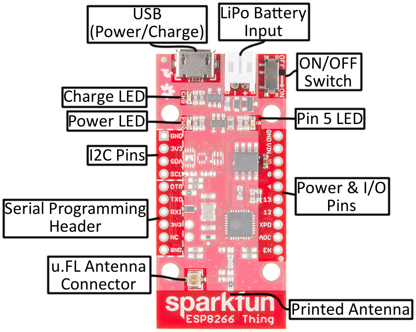
Hardware Overview
The ESP8266 Thing is a relatively simple board. The pins are broken out to two parallel,
breadboard-compatible rows. USB and LiPo connectors at the top of the board provide power
– controlled by the nearby ON/O switch. And LEDs towards the inside of the board indicate
power, charge, and status of the IC.
Here’s a quick overview of the Thing’s main components:

The Pinout
The Thing’s I/O headers can be broken down into three sections:
Serial Programming Header
This six-pin header will be the main point of contact between the Thing and your development
computer. The pinout of this header matches the extremely common “ TDI header.” That
means you can interface it with either a 3.3V TDI Basic or a 3.3V I/O TDI Cable to program
and debug the Thing.
or a quick breakdown of the pins on this header, consult the table below. If a pin is directly
tied to an ESP8266 I/O, it’ll be noted:
Pin
Label
ESP8266
I O # Notes
DTR
Performs auto-reset, and puts the ESP8266 into bootloader mode.
Connects through a capacitor to RESET, and a buffer to the ESP8266's
GPIO0.
TXO 7 ESP8266 UART1 data output.
RXI 8 ESP8266 UART1 data input.
3V3 By default, this pin does not supply the ESP8266 directly (a jumper on

the back can change that).
NC Not connected to anything on the Thing.
GND Ground (0V).
I2C Header
I 2 C is a very popular communication protocol in the embedded world. Whether you want to
hook the Thing up to a motion sensor, light sensor, digital-to-analog converter, or OLED
display, I2C is often the protocol of choice.
This header includes four pins – all that should be required to connect an I2C device up to the
Thing.
Pin
Label
ESP8266
I O # Notes
GND Ground (0V).
3V3 3.3V
SDA 2 Can either be used as ESP8266 GPIO2 or I2C serial data (SDA).
SCL 14 Can either be used as ESP8266 GPIO14 or I2C serial clock (SCL).
Also used as the SPI clock (SCLK).
This pinout matches that of most of our I2C-based breakout boards, so you can piggyback
them right on top of the Thing.
If you need the extra I/O, instead of I2C, the SDA and SCL pins can be used as GPIO 2 and
14 respectively. The SCL pin also serves as the clock (SCLK) for the ESP8266’s SPI
interface.
General I/O Header
The rest of the power, control, and I/O pins are broken out on the other side of the board.
They are:
Pin
Label
ESP8266
I O # Notes
GND Ground (0V).
VIN USB connected: ~4.5V output LiPo connected (no USB): ~3.7V output
No supply: Can be used as a voltage supply input to the 3.3V regulator.
55 This pin is also tied to the on-board LED.
00
44
13 13 Hardware SPI MOSI
12 12 Hardware SPI MISO
XPD 16 Can be connected to reset to set the ESP8266 into deep sleep mode.
ADC A0 A 10-bit ADC with a maximum voltage of 1V.
EN ESP8266 enable pin. HIGH = on, LOW = off. Pulled HIGH on-board.
What happened to the rest of the GPIO pins? Why the eclectic pin-numbering scheme? We’re
taking what the ESP8266 gives us. Unfortunately, most of the remaining GPIO are connected

to the on-board SPI flash memory IC, which stores the ESP8266’s program memory and
potentially other data.
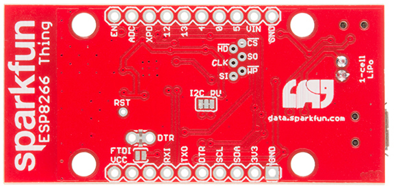
Back of the Thing
lipping the Thing over revels a few trace jumpers and test points, which you may find handy
for your application. (Plus a friendly Phant.io logo, to remind you about our data storage
service on data.sparkfun.com.)
Jumpers
Jumper
Label
Default
Setting Notes
DTR Closed Allows for auto-reset while programming the ESP8266, but makes
serial debugging difficult.
I2C PU Closed Connects 10kΩ pull-up resistors to the SDA and SCL pins.
FTDI VCC Open Connects the 3V3 pin on the serial header directly to the
ESP8266's 3.3V supply.
Of these jumpers, the DTR one is the most commonly modified. The DTR output of the TDI
Basic is used for two purposes: to reset the ESP8266 and pull GPIO0 low (putting the chip in
bootloader mode). Keeping this jumper closed enables programming, but makes debugging
via the Serial Monitor difficult, as the board will reset into bootloader mode whenever the
terminal opens. Using and modifying this jumper is discussed later in this tutorial.
The TDI_VCC jumper defaults to open to ensure that, if a 3.3V Logic (5V power) TDI
Cable is used to program the Thing, 5V isn’t accidentally delivered to the IC. Also, most 3.3V
TDI boards don’t have a lot of juice to supply on the 3.3V bus (they often supply about 50mA
max).

Test Points
These pins are made available just in case they become necessary to your project. The six
pins bundled up together are connected to the Thing’s on-board SPI flash memory, but if you
really need the extra GPIO, or want to experiment with the pins, they’re available.
The RST pin is more useful, but we didn’t leave room to break it out – at least not
directly. RST is tied through a 0.1µ capacitor to the DTR pin, to allow for automatic reset
during programming. or many applications that need the RST pin, toggling the DTR pin
works as well. Putting the ESP8266 into deep sleep is one such application.
Selecting the Antenna
The Thing’s default Wi i antenna is a PCB trace antenna based on this TI app note. It’s cost-
effective and actually works really well!
If you need to connect a more sensitive antenna to the chip, a U. L connector is also
available on the board, but isn’t connected by default to the ESP8266’s antenna pin. To
connect this antenna to the chip, you’ll need to heat up the 0Ω resistor and rotate it 90°:
An (ugly, uncleaned) resistor swapped from printed antenna to U. L antenna.
A soldering iron, pair of tweezers, (2) steady hands, and good set of eyes should be enough
to accomplish the task.

Why Are There Unpopulated Parts?
We initially set out to make the Thing a secure, common-sensor base station. The empty pads
you see are landing spots for three unique IC’s:
•ATECC108A – A “full turnkey Elliptic Curve Digital Signature Algorithm (ECDSA)
engine”, which can be used for unique serial numbers, hashing, key storage, or
random numbers. A great start to securing your IoT project!
•TMP102 Temperature Sensor – A simple, 12-bit, digital temperature sensor.
•TSL2561 Light Sensor – A nifty luminosity/light sensor.
•Plus a few footprints for decoupling capacitors.
After a late change of heart, we decided to keep the board as low cost as possible (that’s the
ESP8266’s best feature!), while leaving the option for later expansion. The pads are still there.
If you want to add any of these components, hopefully all you should need is a hot air
station (maybe probably not a Heaterizer) and some tweezers.
Powering the Thing
The Thing provides for two methods of power delivery: USB or LiPo. The USB connector on
the Thing is of the Micro-B variety. A micro-B cable plugged into either a computer USB port
or a 5V USB Wall Wart can power the Thing.
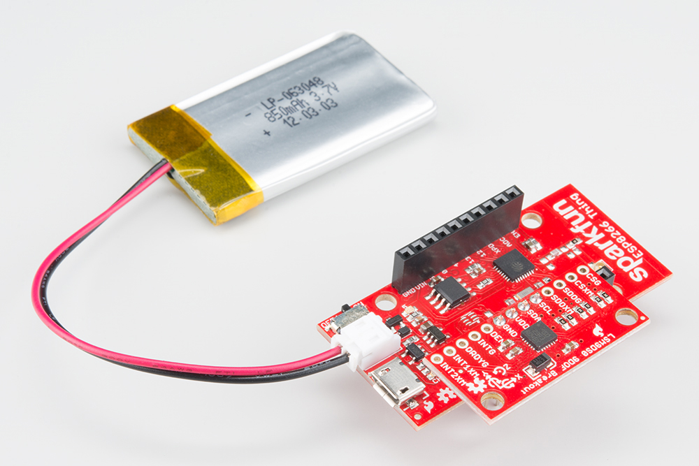
Any of our single-cell LiPo batteries will also work to power the Thing – they all have the same
2-pin JST connector.

Add an 850mAh LiPo and an LSM9DS0 9Do IMU to the Thing, to create an IoT motion
sensor.
If both USB and LiPo are connected to the Thing, it’ll take power from the USB port and
charge the LiPo battery at up to 500mA.
Electrical Characteristics
The ESP8266’s maximum voltage is 3.6V, so the Thing has an onboard 3.3V regulator to
deliver a safe, consistent voltage to the IC. That means the ESP8266’s I/O pins also run at
3.3V, you’ll need to level shift any 5V signals running into the IC.
The input to this regulator can either be delivered by USB, LiPo battery, or through
the VIN pin.
Max Input Voltage: If you supply power to the board through the VIN, make sure the voltage
does not exceed 6V. That's the maximum input voltage of the AP2112K-3.3V regulator the
board uses.
Alternatively, if you have an external, regulated, supply you’d like to deliver directly to the
ESP8266, you can supply that voltage through the 3V3 pin (on the I2C header). While this
voltage doesn’t have to be 3.3V, it must be within the range of 1.7-3.6V.
Current Ratings
On average, the Thing pulls about 80mA. Wi i transmits and receives can momentarily
increase that draw. Here’s a table, transcribed from the ESP8266 datasheet, with some of the
more common current characteristics.
Parameter Typica
lMax Unit
Transmit 802.11b (1 Mbps) 215 mA
Transmit 802.11b (11 Mbps) 197 mA
Transmit 802.11g (54 Mbps) 145 mA
Transmit 802.11n 135 mA
Receive 802.11b 60 mA
Receive 802.11g 60 mA
Receive 802.11n 62 mA
Standby 0.9 mA
Deep Sleep 10 µA
Maximum I/O Pin Drive
Capability 12 mA
If your application requires maximum battery life, you’ll likely need to make liberal use of the
ESP8266’s deep sleep functionality. That’ll be covered later in this tutorial.

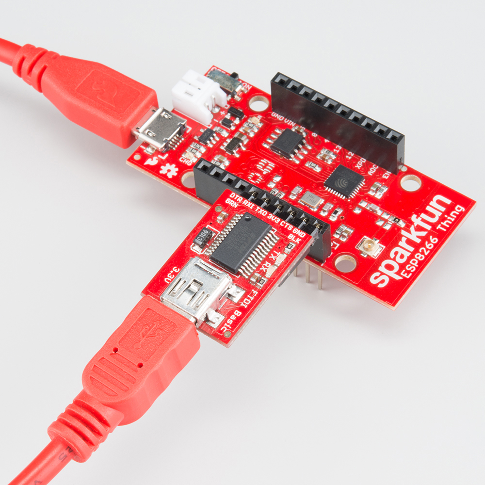
Programming the Thing
The ESP8266 has a built-in serial bootloader, which allows for easy programming and re-
programming. You don’t need a specialized, expensive programmer – just a simple, USB-to-
Serial converter.
We use a 3.3V TDI Basic to program the Thing, but other serial converters with 3.3V I/O
levels should work (e.g. TDI SmartBasic, TDI Cable 5V VCC-3.3V I/O, T231X Breakout.
The converter does need a DTR line in addition to the RX and TX pins.
The TDI Basic’s 6-pin header matches up exactly to the Thing’s 6-pin serial port header. To
set up for programming, simply connect the TDI directly to this port – take care to match up
the DTR and GND pins!
If you’re short on USB ports, the Spark un Cerberus Cable might be just what you need.
Otros manuales para ESP8266
3
Tabla de contenidos
Otros manuales de Enrutador inalámbrico de sparkfun


