Sparkfun Electronics RedBot Manual de usuario

Getting Started with the RedBot a
learn.sparkfun.com tutorial
Available online at: http://sfe.io/t110
Contents
Introduction
Hardware
Arduino Library
Example
Resources and Going Further
Introduction
The RedBot is robotic development platform capable of teaching basic robotics and sensor
integration! Based on the SparkFun RedBoard and programmable in the Arduino environment, the
RedBot has all the I/O you need to make a small robot in no time at all. The RedBot family consists
of the RedBot Mainboard (motor driver and main controller), sensor modules and add-ons, and The
RedBot Kit.
We've also written a comprehensive Arduino library supporting the existing peripherals, which will
Page 1 of 19

be expanded to support additional peripherals as we add them. Once you've installed the library,
you can program the RedBot using the "Arduino Uno" board option--no board definition files
needed.
Suggested Reading
If you still need to assemble your RedBot, visit our RedBot Assembly Guide for detailed
instructions.
Please Note: The RedBot Assembly Guide also includes instructions on how to hook up Dagu’s
Wheel Encoder (not included in the RedBot Kit).
We also have a RedBot Experimental guide that will help you get your RedBot moving and doing
cool things!
Before you go any further, you should probably make certain that you're familiar with these other
topics:
What is an Arduino? - Since the RedBot is based off the Arduino platform, it's a good idea to
understand what that means.
Installing the Arduino IDE - If you don't have the Arduino software installed, this guide will
help you out.
Installing an Arduino Library - To get the most out of the RedBot, you'll want to install our
RedBot library. This tutorial will show you how.
Accelerometer basics - One of the core sensors for the RedBot is an accelerometer. To find
out more about accelerometers, check out this guide.
Analog to digital conversion - Many useful sensors for the RedBot will be analog. This guide
will help you interface with them and make the most of the data you get back.
Pulse width modulation (PWM) - The RedBot includes two headers with PWM signals, and
uses PWM to control the speed of the motors. It's probably a good idea to be familiar with the
concept.
I2C - The RedBot Accelerometer, which ships with the RedBot kit, uses I
2C to communicate
with the RedBot. While the accelerometer is accessible through the library with no knowledge
of I2C required, if you want to get more out of it, you can check out this tutorial.
Exploring XBees and XCTU - If you want to add remote controllability to the RedBot, XBees
are the way to go. This tutorial will help show you how to set them up.
Hardware
RedBot Mainboard
Page 2 of 19

The RedBot Mainboard was designed to be as versatile as possible. It has banks of 3-pin I/O break-
outs for easily connecting up LEDs, Sensors, or motors. It also has an integrated [H-Bridge Driver](
(https://cdn.sparkfun.com/assets/learn_tutorials/1/1/0/TB6612FNG.pdf) chip. While we have
developed an integrated library for the RedBot, if you want to drive the motors manually - here are
the pin outs for the Motor Driver:
LEFT MOTOR:
Control 1 - Pin 2
Control 2 - Pin 4
Motor PWM (Speed) - Pin 5
RIGHT MOTOR:
Control 1 - Pin 7
Control 2 - Pin 8
Page 3 of 19

Motor PWM (Speed) - Pin 6
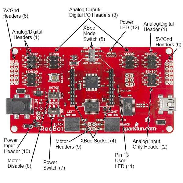
Here's a quick tour of the hardware that's on the board:
1. Analog/digital headers - These three headers provide one I/O pin, which can be used for
analog input as well as digital input or output, as well as 5V power and ground. In addition, the
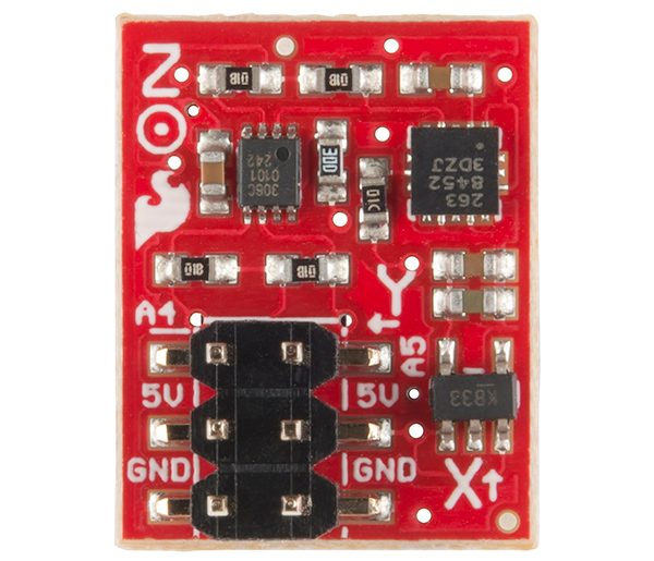
header with A4 and A5 can be used for connecting I2C devices; the RedBot Accelerometer is
designed to solder directly to this header, making connecting an accelerometer a snap.
2. Analog input header - This header provides an additional two analog input pins. These pins
can't be used for digital signals, however.
3. Analog output/digital header - These two headers provide four pins which can be used for
either PWM output or regular digital I/O. Note that the power supply for these headers is
connected directly to the battery, providing extra umph for servo motors, but devices
expecting 5V should not be connected directly to them!
4. Wireless Socket - The RedBot has a socket for an XBee module, providing easy wireless
interfacing.
5. XBee Mode Switch A switch allows you to select whether the XBee communicates via the
standard serial I/O pins (0 and 1, accessible through the built in Serial command set) or via
pins 14 and 15 (A0 and A1), using the SoftwareSerial library. Using the software mode will
consume two of your analog inputs, however.
6. 5V / GND Headers - Headers are available to allow the user to tap off the 5V and ground
signals.
7. Power Switch - A power switch puts the board into a very low power consumption mode
(microamps or less) allowing you to turn the board off without pulling the power connection.
8. Motor Disable Switch - A motor disable switch allows you to turn off the motor driver so you
can program the board without having it drive all over.
9. Motor Headers - Headers are available to easily connect up the right and left side motors.
The motor control is powered by the TB6612FNG Motor Driver.
10. Power Input Header - A header has also been provided to allow you to access the input
supply, either for purposes of driving additional circuitry or to allow more flexibility than the
standard barrel jack does for power sources.
11. DEBUG LED (pin 13) - An LED is connected to pin 13 to allow basic sanity checks that code
is loading and running on the board.
12. Power LED - A power LED will remain lit whenever the power switch is active.
Here's a quick Example program to test your RedBot out with. It spins the left motor forward and
reverse, and the spins both motors forward and reverse.
Page 4 of 19

Push the small reset button to restart the program.
language:c
/*******************************************************************************
/ SimpleRedBotDrive Code - no libraries
/
/ Simple example code showing how to spin the right and left motors and braking.
/ This example requires no libraries to run, and has all of the pins used on the
/ RedBot Mainboard defined.
/
/ Before uploading this code to your RedBot, make sure that the RedBot is in a safe
/ place. It will start moving immediately after you upload the program. We suggest
/ placing the RedBot on it's end so that the wheels are up.
/
/ Push the small reset button on the board to run the program again.
/
/ Note: The RedBot Mainboard programs as an Arduino Uno
/******************************************************************************/
// H-Bridge motor driver pins
#define L_CTRL1 2
#define L_CTRL2 4
#define L_PWM 5
#define R_CTRL1 7
#define R_CTRL2 8
#define R_PWM 6
// XBee SW_Serial pins
#define SW_SER_TX A0
#define SW_SER_RX A1
/*******************
/ setup function
/*******************/
void setup()
{
Serial.begin(9600);
pinMode(L_CTRL1, OUTPUT); // used as a debug pin for an LED.
pinMode(L_CTRL2, OUTPUT); // used as a debug pin for an LED.
pinMode(L_PWM, OUTPUT); // used as a debug pin for an LED.
pinMode(R_CTRL1, OUTPUT); // used as a debug pin for an LED.
pinMode(R_CTRL2, OUTPUT); // used as a debug pin for an LED.
pinMode(R_PWM, OUTPUT); // used as a debug pin for an LED.
pinMode(13, OUTPUT); // used as a debug pin for an LED.
// spin the left Motor CW
leftMotor(255);
delay(2000);
leftBrake();
delay(1000); // wait for 1000 milliseconds
Page 5 of 19

// spin the left Motor CCW
leftMotor(-255);
delay(2000);
leftBrake();
delay(1000); // wait for 1000 milliseconds
// spin both motors (drive forward) -- left CW, right CCW
leftMotor(255);
rightMotor(-255);
delay(2000); // wait for 2000 milliseconds
leftBrake();
rightBrake();
// spin both motors (drive in reverse) -- left CCW, right CW
leftMotor(-255);
rightMotor(255);
delay(2000); // wait for 2000 milliseconds
leftBrake();
rightBrake();
}
/*******************
/ loop function
/*******************/
void loop()
{
// no code here. All driving code is in the setup() -- so that it runs just once.
}
/*******************************************************************************/
void leftMotor(int motorPower)
{
motorPower = constrain(motorPower, -255, 255); // constrain motorPower to -255 to +255
if(motorPower >= 0)
{
// spin CW
digitalWrite(L_CTRL1, HIGH);
digitalWrite(L_CTRL2, LOW);
analogWrite(L_PWM, abs(motorPower));
}
else
{
// spin CCW
digitalWrite(L_CTRL1, LOW);
digitalWrite(L_CTRL2, HIGH);
analogWrite(L_PWM, abs(motorPower));
}
}
/*******************************************************************************/
void leftBrake()
{
// setting both controls HIGH, shorts the motor out -- causing it to self brake.
Page 6 of 19

digitalWrite(L_CTRL1, HIGH);
digitalWrite(L_CTRL2, HIGH);
analogWrite(L_PWM, 0);
}
/*******************************************************************************/
void rightMotor(int motorPower)
{
motorPower = constrain(motorPower, -255, 255); // constrain motorPower to -255 to +255
if(motorPower >= 0)
{
// spin CW
digitalWrite(R_CTRL1, HIGH);
digitalWrite(R_CTRL2, LOW);
analogWrite(R_PWM, abs(motorPower));
}
else
{
// spin CCW
digitalWrite(R_CTRL1, LOW);
digitalWrite(R_CTRL2, HIGH);
analogWrite(R_PWM, abs(motorPower));
}
}
/*******************************************************************************/
void rightBrake()
{
// setting both controls HIGH, shorts the motor out -- causing it to self brake.
digitalWrite(L_CTRL1, HIGH);
digitalWrite(L_CTRL2, HIGH);
analogWrite(R_PWM, 0);
}
Magician Chassis
Page 7 of 19

The Magician Chassis is an economical robot platform with a lot of versatility. It features two
gearmotors with 65mm wheels and a caster. The chassis plates are cut from acrylic with a wide
variety of mounting holes for sensors, controllers, power, etc. The chassis does require some basic
assembly but detailed instructions are included.
RedBot Line Follower Sensor
Page 8 of 19

The Line Follower sensor is an add-on for your RedBot that gives your robot the ability to detect
lines or nearby objects. The sensor works by detecting reflected light coming from its own infrared
LED. By measuring the amount of reflected infrared light, it can detect transitions from light to dark
(lines) or even objects directly in front of it.
The sensor has a 3-pin header which connects directly to the RedBot Mainboard via female to
female jumper wires. Use the included RedBot library to detect lines or objects. A mounting hole
lets you easily connect one or more of these to the front or back of your robot chassis.
RedBot Accelerometer
The Accelerometer sensor is an add-on for your RedBot that provides bump and motion detection.
The sensor works by measuring acceleration forces on the x, y, and z axis. By measuring the
amount of acceleration (or lack there of) your robot can get a better understanding of its
movements.
The sensor has a 2x3 unpopulated footprint which connects directly to the RedBot Mainboard via a
female header. You can also solder the sensor directly to the headers on the Mainboard if you wish.
RedBot Whisker Bumper
Page 9 of 19

The Whisker Bumper is a very simple sensor comprised of a piece of music wire that closes a
contact when bent and a circuit board to interface it to the RedBot. We ship the music wire straight,
so you'll have to bend it to suit your application; the example shown above is only one way to do it.
RedBot Buzzer Board
Page 10 of 19
Manuales populares de Robótica de otras marcas

STEMCenter USA
STEMCenter USA Pi-Bot v2.00 Manual de usuario

SunFounder
SunFounder PiDog Manual de usuario

Universal Robots
Universal Robots UR5 Manual de usuario

Universal Robots
Universal Robots E Series Manual de usuario

YASKAWA
YASKAWA MOTOMAN-MPL80 II Manual de usuario

EFORT
EFORT ECR5 Manual de instrucciones


