South Galaxy G5 Manual de usuario

- 1 -
SOUTH G5 GNSS Positioning System
User Manual

- 2 -
Contents
Contents .......................................................................................................................................- 2 -
Chapter Ⅰ Preface ......................................................................................................................... - 4 -
§1.1 Introduction ................................................................................................................. - 4 -
§1.2 Applications .................................................................................................................- 4 -
§1.3 Main Features ..............................................................................................................- 5 -
ChapterⅡHardware Component ...............................................................................................- 6 -
§2.1 Receiver components .................................................................................................. - 6 -
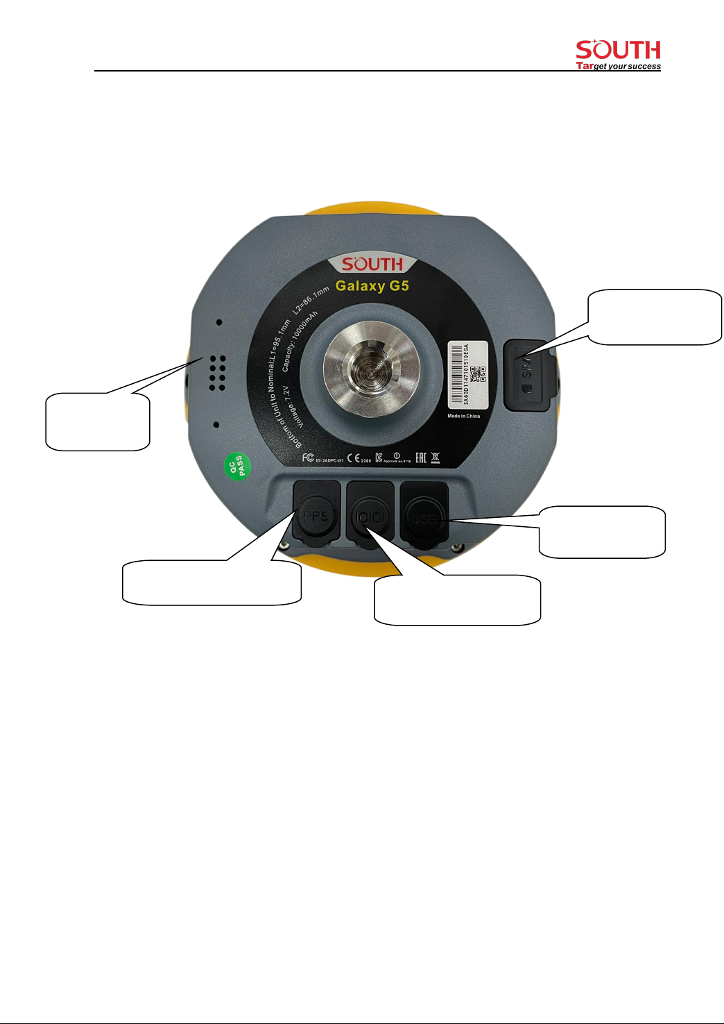
§2.2 Bottom Components ....................................................................................................- 7 -
§2.3 Indicators and Keypad .................................................................................................- 8 -
§2.4 Touch screen ................................................................................................................- 9 -
§2.5 Receiver Menu ............................................................................................................ - 9 -
§2.5.1 Main display interface ......................................................................................- 9 -
§2.5.2 Main menu ......................................................................................................- 11 -
§2.5.3 Power off, Reset, Set default and Self-check .................................................- 12 -
§2.5.4 Set work mode ................................................................................................- 13 -
§2.5.5 Set datalink mode ...........................................................................................- 16 -
§2.5.6 System option .................................................................................................- 19 -
§2.5.7 WIFI config .................................................................................................... - 21 -
§2.5.8 USB mode config ........................................................................................... - 21 -
ChapterⅢWeb UI Management ..............................................................................................- 22 -
§3.1 Overview ................................................................................................................... - 22 -
§3.2 Access by WiFi ..........................................................................................................- 22 -
§3.3 Access by USB .......................................................................................................... - 23 -
§3.4 Web UI main interface .............................................................................................. - 24 -
§3.4.1 Status .............................................................................................................. - 26 -
§3.4.2 Configuration ................................................................................................. - 27 -
§3.4.3 Satellite Information ...................................................................................... - 33 -
§3.4.4 Data Record ....................................................................................................- 35 -
§3.4.5 Data Transfer .................................................................................................. - 36 -
§3.4.6 Network Config ..............................................................................................- 40 -
§3.4.7 Radio Config .................................................................................................. - 43 -
§3.4.8 Firmware Update ............................................................................................- 45 -
§3.4.9 Track Manage .................................................................................................- 48 -
§3.4.10 Coordinate System ....................................................................................... - 49 -
§3.4.11 Online Service .............................................................................................. - 49 -
§3.4.12 User Management ........................................................................................ - 50 -
§3.4.13 System log ....................................................................................................- 50 -

- 3 -
ChapterⅣAccessories ............................................................................................................. - 51 -
§4.1 Instrument Case .........................................................................................................- 51 -
§4.2 Charger ...................................................................................................................... - 51 -
§4.3 Cable ..........................................................................................................................- 52 -
§4.4 UHF Antenna .............................................................................................................- 52 -
§4.5 Other Accessories ......................................................................................................- 52 -
G5 Specifications ...................................................................................................................... - 53 -

- 4 -
Chapter Ⅰ Preface
Read this chapter, you will have a brief knowledge of SOUTH Company and G5
measurement system.
§1.1 Introduction
Welcome to South Surveying & Mapping Technology CO., LTD, which is China’s leading
manufacturer of surveying equipment including GNSS receivers and Total Stations. To know
more about SOUTH, please visit our official website https://www.southinstrument.com/
This manual takes G5 positioning system for example, to explain how to install, set up and uses
the RTK system as well as the use of the accessories. We recommend that you read these
instructions carefully before using the instrument.
§1.2 Applications
Control Survey: dual-band (dual-frequency) system static measurements can accurately
complete the high-precision deformation observation, photo-control point measurement.
Highway Survey: quickly complete the encryption of the control points, road topographic
mapping, cross-section measurement, profile measurement with K-survey.
CORS Application: provide more stable and convenient data link for field operations. It is
seamlessly compatible with all types of domestic CORS applications.
Data acquisition measurement: perfect match SOUTH various measurement software to do
quick and easy data acquisition.
Stakeout shot:large-scale point, line, plane lofting.
Electric Power Measurement:power line measurement orientation, ranging, angle calculation.
Marine application:oceanographic research, dredging, piling, inserted row, making the marine
operations more convenient and easier.

- 5 -
§1.3 Main Features
All Constellations and More Channels
With 1598 channels, G5 is capable to track signal from 5 satellite constellations , process signal
of up to 16 frequencies and provide stable and reliable accuracy.
More Powerful and More Durable
Thanks to the 3W Farlink radio, when it works as an UHF base station G5 is able to
transmit correction data farther than others, in optimal condition the working range
can be 10 to 15 km.The shock-resistant frame, water-proof frame all have been enhanced, now
the overall proof level is IP68.
Superior Endurance, Up to 25 hours working
The newly developed power management system allows G5 to work for 10 to 25
hours and can be recharged by a type-C connector.
Color Touch Screen, Makes Workflow Simpler
Users can operate G5 by touch screen and key buttons, easy and fast.
RTK-Keep
When G5 loses the RTK correction data source from base station, this function will
help receiver to maintain the precise position for a few minutes.
L-band Correction, 4-10cm PPP
G5 is able to receive B2b signal via L-band, and perform a single point positioning.
It is a great help to surveyors who work in particularly difficult areas. This service is
available in 2022 from Asian-Pacific region.

- 6 -
ChapterⅡHardware Component
Reading this chapter, you can grasp the components, installation and the function of
G5 positioning system
§2.1 Receiver components
UHF antenna port
Key pad
LCD touch screen
NFC

- 7 -
§2.2 Bottom Components
Type-c port: USB port, OTG interface and Ethernet port..
5-Pin port:
1. As a power port connected with an external power supply device.
2. As a differential transmission port connected with an external radio.
3. As a serial port to check data output and debug.
PPS Port:N/A
Speaker:Voice broadcast.
SIM Slot:Insert SIM card.
○
4Speaker
○
2 5 PIN LEMO port
○
3PPS port
○
1Type-C port
○
5SIM slot

- 8 -
§2.3 Indicators and Keypad
Ref
Component
Description
Power Button
1) Power on/off
2) Select menu
3) In lowest menu: short press for select, long press for
confirmation
Bluetooth Indicator
Light on blue when Bluetooth connected
Data Indicator
Flash green when Fixed solution.
Flash red when not Fixed with the correction signal.
No Flash when no correction data.
Function Key
Shift between menus.
Keypad operation:
Fn key: Shift between options
PWR key:
1) Short press: select the option
2) Long press: to Power off (Reset, Set default, Self-check) receiver
3) Long press: to accept the configuration (when at the lowest menu), just like swiping down the
touch screen.
Press any key (or click on touchscreen) will wake up screen if screen sleeps.

- 9 -
§2.4 Touch screen
The receiver can be operated from both keypad and touch screen. By swiping the screen,
receiver can be configured.
1. Swipe right /left: to shift between options (or press Fn key to shift between options)
2. Tap screen: for selection (or short press PWR key for selection)
3. Swipe down:
----To bring up system menu [Power off], [Reset], [Set default], [Self-check] when it is at main
display interface
---- In lowest level menu: swipe screen down to accept the configuration (or long press PWR key
to accept the configuration).
4. Swipe up
Return from sub-menu to previous menu.
§2.5 Receiver Menu
§2.5.1 Main display interface
There are 2 main display interfaces: [Coordinates display interface], [Satellite display interface].

- 10 -
Icons in the Coordinates display interface
1) In static mode:
2) In Base mode:
3) In Rover mode:
Coordinates and
satellites
Static recording
Work in
static mode
Datalink: WIFI
Differential correction
data format
Datalink status
Solution status
Datalink: WIFI
Datalink status
Tabla de contenidos
Otros manuales de GPS de South


