Snell Advanced Media Vega 200 Manual de usuario

www.s-a-m.com
Vega 100
Series Routers
Quick Setup Guide

Vega 100 Series Routers Quick Setup Guide
Issue 4 Rev 3 Page2
In this Quick Setup guide, we’ll cover the basic steps to get your Vega 100 Series router ‘up
and running’ and controlling signal routes.
For full configuration and operational details, please refer to the user manual which
accompanies the product.
What’s Inside
Introduction 3
Safety and EMC 4
Unpacking 7
Power & Status Check 9
Browser Login 11
XY Panel 14
External Control 15
Updating Vega 15
Introduction
Page3 © 2016 SAM
Introduction
Vega is a new concept in signal routing with key additional benefits:
• Asymmetric router configurations
• Coaxial copper or fiber connectivity
• Extensive redundancy options
• Ultra compact frame
•Comprehensive set of ‘soft’ and/or ‘hard’ control options
This Quick Setup guide takes you through the simple steps to enable control of signal
routing in a Vega 100 Series router using a PC. After unpacking the Vega router, you’ll be
up and running within minutes.
Please refer to the Vega 100 Series user manual for advanced setup and configuration.
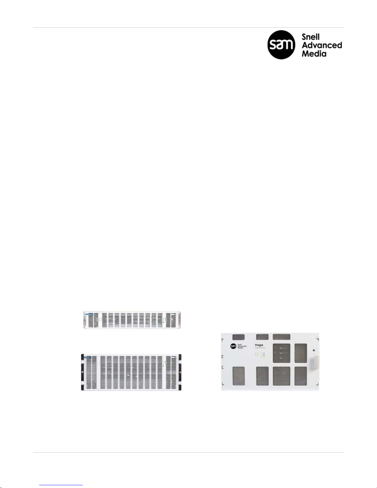
Vega 100 Series Routers
The Vega 100 Series offers the following router models:
• Vega 200 (up to 96 ports).
• Vega 400 (up to 192 ports).
• Vega 700 (up to 432 ports).
Vega 400 Vega 700
Vega 200

Vega 100 Series Routers Quick Setup Guide
Issue 4 Rev 3 Page4
Safety and EMC
For comprehensive safety information please see the Vega 100 Series user manual.
Safety Standards
This equipment complies with the following standards:
EN60950-1: 2006
Safety of Information Technology Equipment Including Electrical Business Equipment.
UL1419 (3rd Edition) - UL File E193966
Standard for Safety Professional Video and Audio equipment.
EMC Standards
This unit conforms to the following standards:
EN55103-1:2009 (Environment E4)
Electromagnetic Compatibility, Product family standard for audio, video, audio-visual and
entertainment lighting control apparatus for professional use. Part 1. Emission
EN55103-2:2009 (Environment E2)
Electromagnetic Compatibility, Product family standard for audio, video, audio-visual and
entertainment lighting control apparatus for professional use. Part 2. Immunity
Federal Communications Commission Rules, 47 CFR: 2009, Part 15, Subpart B (Class A)

Safety and EMC
Page5 © 2016 SAM
Mains Safety
• Caution: Double Pole/Neutral Fusing (Vega 200 and 400 models).
• This equipment has more than one power supply cord. To reduce the risk of
electrical shock, disconnect all the power supply cords before servicing.
• Isolate the unit from other product outputs before servicing.
• The IEC power inlets are the mains disconnection devices for this unit.
• To reduce the risk of electric shock, plug each power supply cord into separate
branch circuits employing separate service grounds.
• Ensure that all of the router modules and cards are correctly installed and firmly
seated before powering on the Vega router.
Laser Safety EN60825-1 (2001)
• Caution: use of controls or adjustments or performance of procedures other than
those specified herein may result in hazardous radiation exposure. Viewing the
laser diode with the optical fiber removed and with the aid of optical magnifiers
may be hazardous.
• This product is a Class 1 laser product
(output power <15mW) at 1270 nm to 1610 nm with a beam divergence >30mrad.

Vega 100 Series Routers Quick Setup Guide
Issue 4 Rev 3 Page6
C
Figure 2: Vega 200 & 400 Transit bracket screws (Vega 400 shown)
B
Turn Right to lock
Turn Left to unlock
Figure 3: Vega 700 front door fastener
Figure 1: Vega 200 & 400 front door (Vega 200 shown)
A
(1 of 2)
F
E
G
Figure 6: Vega 700 Transit Bracket storage on back of Vega 700 front door
Figure 4: Vega 700 PSU Bracket storage
Figure 5: Vega 700 Transit Bracket screws
H
D

Unpacking
Page7 © 2016 SAM
Unpacking
Vega’s shipping carton includes:
•An Information Pack (Including this printed Quick Setup Guide and Vega 100 Series
manuals on the CD)
•The Vega 100 Series Router
• Up to two IEC mains cords
•Up to two USB ‘memory sticks’ (Including ‘reboot’ program for lost IP address’. One
per controller. Please refer to user manual)
Unpack the Vega router chassis. Place it on a suitable flat surface for testing.
Vega 200 & 400 Transit Brackets:
Loosen the two captive fasteners on the Vega 200/400 front door (A).
Open the Vega front door by pulling the door out and swinging it down.
Loosen the four transit bracket screws (B) and slide bracket to the right and remove it.
Re-tighten the four screws.
Unscrew the single transit bracket screw (C) and remove the bracket.
Put both transit brackets, the single screw and the packing in the Vega shipping carton, in
case subsequent transportation is required.
Close the Vega 200/400 front door and re-tighten the fasteners.
Vega 700 Transit Brackets:
Unlock the Vega 700 quarter-turn door fastener (D). Open the door.
Unscrew the PSU Transit Bracket screw (F) and remove Bracket. Rotate the bracket 90
degrees and screw it into its storage position (E in Figure 4).
Unscrew the two Vega Card Transit Bracket screws (G) and remove the bracket. Secure
the bracket in its storage position on back of door (H).
Put Vega 700 packing in its shipping carton, in case subsequent transportation is required.
Close the Vega 700 front door and lock the quarter-turn door fastener.

Vega 100 Series Routers Quick Setup Guide
Issue 4 Rev 3 Page8
Figure 7: Vega 200 & 400 Rear IEC Power Inlets
Figure 10: Vega 700 Rear IEC Power Supply Inlets
PSU 2, rear lower inlet (for Dual PSUs only)
PSU 2
left-hand rear
inlet.
(for Dual PSUs
only)
if no PSU 2 fitted, “Off”
Figure 8: Vega 200 & 400 Front LEDs (Vega 200 shown)
“Off”
“Off”, if no second Crosspoint fitted
“Off”, if no second
Controller fitted
PSU 1
right-hand
rear inlet.
(for Single &
Dual PSUs)
“Off”
“Off”,
if no second
Controller fitted
“Off”,
if no second
Crosspoint fitted
if no PSU 2 fitted, “Off”
Figure 9: Vega 700 Front LEDs
PSU 1, rear upper inlet (for Single & Dual PSUs)

Power & Status Check
Page9 © 2016 SAM
Power & Status Check
Power
A Vega 100 Series router is supplied with either one or two Power Supply Units (PSUs).
Connect the supplied IEC mains cord to the PSU 1 rear inlet.
If a second PSU is fitted,
connect a second IEC mains cord to the PSU 2 rear inlet.
Connect the IEC cord(s) to a live mains source; the Vega will power up.
Front LED Status
Check the status of the front LED indicators after power up.
See Figures 8 (Vega 200 and 400) and Figure 9 (Vega 700).
Check the LEDs are correct for the PSU, Controller (CTL) and Crosspoint (XP) redundancy
router options fitted.
Troubleshooting
If the LED colors displayed are not as shown in the figures, please ensure that:
1. The mains supply is on and the power cord(s) are connected securely.
2. The PSU(s) and cards are all firmly seated.
If further support is required contact your local SAM representative. Contact details can be
found by visiting www.s-a-m.com/support/247-support-contact-detailsand clicking on
the Support tab. and clicking on the Support tab.
Note:
For Vega 200 & 400 - see Figure 7 and Figure 8.
For Vega 700 - see Figure 9 and Figure 10.
Vega 100 Series Routers Quick Setup Guide
Issue 4 Rev 3 Page10
CAT5 Cable Assembly
To Network Hub,
Switch or PC.
Vega 200
Vega 400
Vega 700
Figure 11: Rear Ethernet Network ports
Figure 12: Browse to the Vega home page
Enter default IP address
http://172.19.39.150/
and press Return.
Vega unit home page
loads
For information only
subnet mask:
255.255.224.0
Click Connect
Otros manuales para Vega 200
1
Este manual sirve para los siguientes modelos
2
Tabla de contenidos
Otros manuales de Enrutador de red de Snell Advanced Media


Manuales populares de Enrutador de red de otras marcas


NETGEAR
NETGEAR FS526T - Switch Manual de usuario

Korenix
Korenix JetNet 5710G Series Manual de usuario

Automated Logic
Automated Logic ZN551 Manual del propietario

Cisco
Cisco ASR 1000 Series Manual del operador

EnGenius
EnGenius ESR-9710 Manual de usuario

Cisco
Cisco 805 Series Instrucciones de funcionamiento y seguridad