Skipper DB-100-SB Hoja de especificaciones

SKIPPER Electronics AS
Enebakkveien 150 www.skipper.no
P. O. Box 151, Manglerud E-mail: support@skipper.no
0612 Oslo, Telephone: +47 23 30 22 70
Norway Co. reg. no: NO-965378847-MVA
Document no: DM-BDB100-SB
Rev 1003A
Date: 2019-02-12
DB-100-SB
Operation and Installation Manual
Double Bottom Sea Valve

Page 2 of 21 Date: 2019-02-12
SKIPPER Electronics AS DB-100-SB Operation and Installation Manual
Weitergabe sowie vervielfältigung dieser unterlage,
verwertung und mitteilung ihres inhaltes nicht gestattet,
soweit nicht ausdrücklich zugestanden. Zuwiderhandlungen
verpichten zu schadenersatz.
Toute communication ou reproduction de ce document,
toute exploitation ou communication de ou son contenu sont
interdites, sauf autorisation expresse. Tout manquement à
cette règle est illicite et expose son auteur au versement de
dommeges et intèrèts.
Copying of this document, and giving it to others and the use
or communication of contents thereof, are forbidden without
express authority. Offenders are liable to the payment of
damages.
Sin nuestra expresa autorización, queda terminantemente
prohibida la reproducción total o parcial de este documento,
asì como su uso Indebido y/o su exhibición o comunicación
a terceros. De los infractores Se exigirá el correspondiente
resarcimiento de daños y perjuicios.

Page 3 of 21 Date: 2019-02-12
Contents
1. Installation........................................................................................................................................4
2. Space considerations........................................................................................................................6
3. Intermediate Tube ............................................................................................................................7
4. Blanking plate ..................................................................................................................................8
5. Welding the bottom ange ...............................................................................................................9
6. Sea Valve Assembly.......................................................................................................................11
7. Assembling of rst extension tube and sensor...............................................................................12
8. Sensor installation..........................................................................................................................13
9. Clamp Unit mounting ....................................................................................................................14
10. Extension tube mounting order....................................................................................................15
11. Final assembly..............................................................................................................................17
12. Sensor removal.............................................................................................................................18
13. Re-installation..............................................................................................................................19
14. DB-100 Sensors ...........................................................................................................................20
15. 100 mm Double Bottom Ball Valve.............................................................................................21
SKIPPER Electronics AS DB-100-SB Operation and Installation Manual

Page 4 of 21 Date: 2019-02-12
SKIPPER DB (Double Bottom) Sea Valve 100 mm
1. Installation
The SKIPPER DB Sea Valve 100 mm is used for installation of SKIPPER speed log sensors and echo
sounder transducers tted with adaptor for XB-100-XX.
Caution!
Be aware that the Sea Valve contains high precision parts and therefore proper
handling when mounting is essential for the nal result.
When handling the Sea Valve, all lifting devices must be attached on the outside of the
valve. It is very important to not insert any chains, wire, rope or any other device into
the valve chamber. This to avoid damaging and any kind of pollution of the Sea Valve.
Caution must be taken when mounting seavalves that all parts are aligned correctly, and that the inside is
clean. DO NOT use liguid sealants, and DO NOT paint the inside of a valve.
The SKIPPER DB Sea Valve 100 mm is delivered partly assembled for transport. The parts necessary for
nal assembly will be found packed in a box delivered with the Sea Valve. First of all, it must be decided
where the Sea Valve should be installed. Normally, this will be in the fore part of the ship, in the centerline,
or as close to the centerline as possible. Optimal system operation is achieved by tting the transducer/
sensor as deep as possible on the hull.
• The active surface of the sensor must be installed with front face a maximum of +/-1 degree to the ships
horizontal plane. (Speed Logs).
• The active surface of the transducer must be installed with front face a maximum of +/-7 degree to the
ships horizontal plane. (Echo Sounder).
Do not mount transducers close to the bow thruster propeller outlets, or aft of other hull installations (outlets,
vents or other protruding details) who may create aeration or turbulence.
It is necessary to select a part of the hull that is submerged and free from turbulence and aeration under all
load and speed conditions, and to avoid positions where air is trapped in heavy weather.
If a at, horizontal section is not available for transducer tting, the shipyard must construct a suitable bed.
Welding seams in this area should be smoothed and rounded off, in order not to create turbulence or aeration
at speed.
Protect the active element of the transducer/sensors during transport and installation, and
do not paint the surface.
The Sea Valve should be placed in a service accessible place, large enough for installation and disassembly
of the sensor unit. See drawing: “Space considerations”.
SKIPPER Electronics AS DB-100-SB Operation and Installation Manual

Page 5 of 21 Date: 2019-02-12
Important
”Sensors for Speed Log and Echo Sounder are delivered with a xed cable. Needed attention must be
taken to allow easy replacement/pulling of new cable during maintenance”.
SKIPPER Electronics AS can help recommend installation positions if GA-drawings (General
arrangements), lines drawings and frame drawings are made available for study.
Condition.
The welding to hull structures and structural support of the items may be subject to separate approval by
classication societies for each installation on board a ship.
Note: All “Item (X)” references on the following pages, can be found on the drawing “100 mm Double
Bottom Ball Valve” .
SKIPPER Electronics AS DB-100-SB Operation and Installation Manual

Page 6 of 21 Date: 2019-02-12
The Sea Valve should be placed in a service accessible place large enough for installation and disassembly
of the transducer/sensor unit.
2. Space considerations
72 35
380
200
190
SKIPPER Electronics AS DB-100-SB Operation and Installation Manual
Page 7 of 21 Date: 2019-02-12
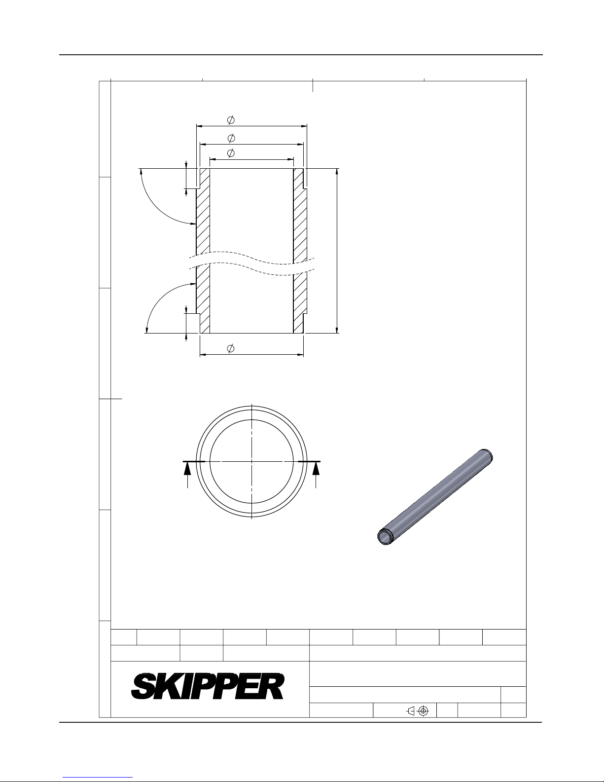
3. Intermediate Tube
A
A
139,7
-
0
1,4
113 max.
155 max.
27
+
0,1
0
27
+
0,1
0
90°
±0,5°
90°
±0,5°
139,7
-
0
0,3
Depend on Bulkhead level
Real view
Scale: 1 : 20
ID: Max. 113mm Min.108mm
* Yard supply
Surface treatment: Red Industrial primer
Flugger 1240 or equal
Basic tube measurements:
OD: Max. 155mm Min.138,5mm
Minimum wall thickness: 12mm
C
2
3
1
4
B
A
D
E
F
Approved by - date
VF 2008.09.10
ST
Designed by - date
1 of 1
Intermediate Tube
Scale
DB-2029
Revision
01
Sheet
Edition date
GT 2015.07.02
Name
Drwg. no.
CN
Checked by
2015.07.01
Material
Steel DIN17121/St52.3N or equal
Eur. projection
Gen. tolerance
1 : 3
ISO2768m
Electronics AS
SKIPPER Electronics AS DB-100-SB Operation and Installation Manual

Page 8 of 21 Date: 2019-02-12
4. Blanking plate
SKIPPER Electronics AS DB-100-SB Operation and Installation Manual

Page 9 of 21 Date: 2019-02-12
5. Welding the bottom ange
• When the position has been decided, a 170 mm hole is cut in the hull, and a 200 mm hole is cut in the
bulkhead (tanktop).
• The bottom ange, Item (1) is welded into the hull. Standard welding practice, methods and procedures
should be observed, but may vary. (See welding notes).
WELDING NOTES!
All bottom parts and anges for welding are precisely machined parts. During welding of these parts
to the ship’s hull plates, careful attention must be paid to avoid construction strain on the bottom
parts and anges.
• Let parts cool down during welding.
• Over heating may change t and form and result in non-conformity with intended sensor/
transducer.
• Welding to thick hull steel plates will exert high stress on bottom parts and anges.
• Especially care must be taken during welding of stainless steel anges.
• Work must be performed by a qualied and certied welder.
Attention:
The bottom ange is a part of the Sea Valve that is machined with high accuracy and it should be
protected after mounting to avoid damage to the bottom ange surfaces. This to avoid leakage. If the
valve is pre-mounted, be sure to protect the valve from being polluted by welding debris.
SKIPPER Electronics AS DB-100-SB Operation and Installation Manual

Page 10 of 21 Date: 2019-02-12
6
8
8
6
• Intermediate ange Item (11) is welded into intermediate tube Item (10). (*Yard supply). Standard welding
practice, methods and procedures should be observed. (See welding notes).
• Blanking plate Item (9) (*Yard supply) is placed over the 200 mm hole in the bulkhead.
• Intermediate tube Item (10) is tread into the blanking plate Item (9) and through the 200 mm hole in the
bulkhead.
• Standard welding practice, methods and procedures should be observed. (See welding notes).
SKIPPER Electronics AS DB-100-SB Operation and Installation Manual
Tabla de contenidos
Otros manuales de Unidad de control de Skipper


Manuales populares de Unidad de control de otras marcas

Festo
Festo Compact Performance CP-FB6-E Manual de lista de piezas

Elo TouchSystems
Elo TouchSystems DMS-SA19P-EXTME Manual de usuario

JS Automation
JS Automation MPC3034A Manual de usuario

JAUDT
JAUDT SW GII 6406 Series Guía rápida

Spektrum
Spektrum Air Module System Manual de usuario

BOC Edwards
BOC Edwards Q Series Manual de usuario


