SimCom Mini PCIe EVB Kit Manual de usuario

Mini PCIe_EVB kit_
User Guide_V1.00

Smart Machine Smart Decision
Mini PCIe _EVBkit_UserGuide_V1.00 2 2014-05-05
Document Title: Mini PCIe EVB kit User Guide
Version: 1.00
Date: 2014-05-05
Status: Release
Document Control ID: Mini PCIe _EVB kit_User Guide_V1.00
General Notes
SIMCom offers this information as a service to its customers, to support application and engineering efforts
that use the products designed by SIMCom. The information provided is based upon requirements
specifically provided to SIMCom by the customers. SIMCom has not undertaken any independent search for
additional relevant information, including any information that may be in the customer’s possession.
Furthermore, system validation of this product designed by SIMCom within a larger electronic system
remains the responsibility of the customer or the customer’s system integrator. All specifications supplied
herein are subject to change.
Copyright
This document contains proprietary technical information which is the property of SIMCom Limited.,
copying of this document and giving it to others and the using or communication of the contents thereof, are
forbidden without express authority. Offenders are liable to the payment of damages. All rights reserved in
the event of grant of a patent or the registration of a utility model or design. All specification supplied herein
are subject to change without notice at any time.
Copyright © Shanghai SIMCom Wireless Solutions Ltd. 2014

Smart Machine Smart Decision
Mini PCIe _EVBkit_UserGuide_V1.00 3 2014-05-05
Contents
Contents..................................................................................................................................................................... 3
Ve r s i o n H i s t o r y .......................................................................................................................................................... 6
1. Mini PCIe EVB ..................................................................................................................................................... 7
2. EVB Accessory...................................................................................................................................................... 9
3. Accessory Interface.............................................................................................................................................. 10
3.1 Adapter Interface ....................................................................................................................................... 10
3.2 Audio Interface .......................................................................................................................................... 11
3.3 SIM card interface ..................................................................................................................................... 12
3.4 Antenna Interface....................................................................................................................................... 13
3.5 UART port interface .................................................................................................................................. 14
3.6 LED Indicator and Switch ......................................................................................................................... 15
4. Test Interface ....................................................................................................................................................... 17
4.1 J2001.......................................................................................................................................................... 17
4.2 J2002.......................................................................................................................................................... 18
4.3 J2003.......................................................................................................................................................... 19
5. EVB and Accessory ............................................................................................................................................. 20
6. Illustration: .......................................................................................................................................................... 21
6.1 Power on module ....................................................................................................................................... 21
6.2 Registering Network and making a call..................................................................................................... 21
6.3 Downloading ............................................................................................................................................. 26
6.3.1 USB Port Specification............................................................................................................ 26
6.3.2 Firmware Update ..................................................................................................................... 27
7. Appendix.............................................................................................................................................................. 35
I. Related Documents.................................................................................................................................. 35
II. Safety Caution ......................................................................................................................................... 35

Smart Machine Smart Decision
Mini PCIe _EVBkit_UserGuide_V1.00 4 2014-05-05
Table Index
TABLE 1: 5V ADAPTER INTERFACE .......................................................................................................................... 10
TABLE 2: HEADSET INTERFACE................................................................................................................................11
TABLE 3: EARPHONE INTERFACE:............................................................................................................................ 11
TABLE 4: UIM CARD SOCKET .................................................................................................................................... 12
TABLE 5: MAIN UART PORT........................................................................................................................................ 14
TABLE 6: DEBUG UART PORT:.................................................................................................................................... 15
TABLE 7: WORKING STATE OF LED AS LIST:.......................................................................................................... 15
TABLE 8: FUNCTION OF SWITCH .............................................................................................................................. 16
TABLE 9: J103 INTERFACE PIN LIST.......................................................................................................................... 17
TABLE 10: J2002 INTERFACE PIN LIST...................................................................................................................... 18
TABLE 11: J2003 INTERFACE PIN LIST...................................................................................................................... 19
TABLE 12: RELATED DOCUMENTS ........................................................................................................................... 35
TABLE 13: SAFETY CAUTION..................................................................................................................................... 35

Figure Index
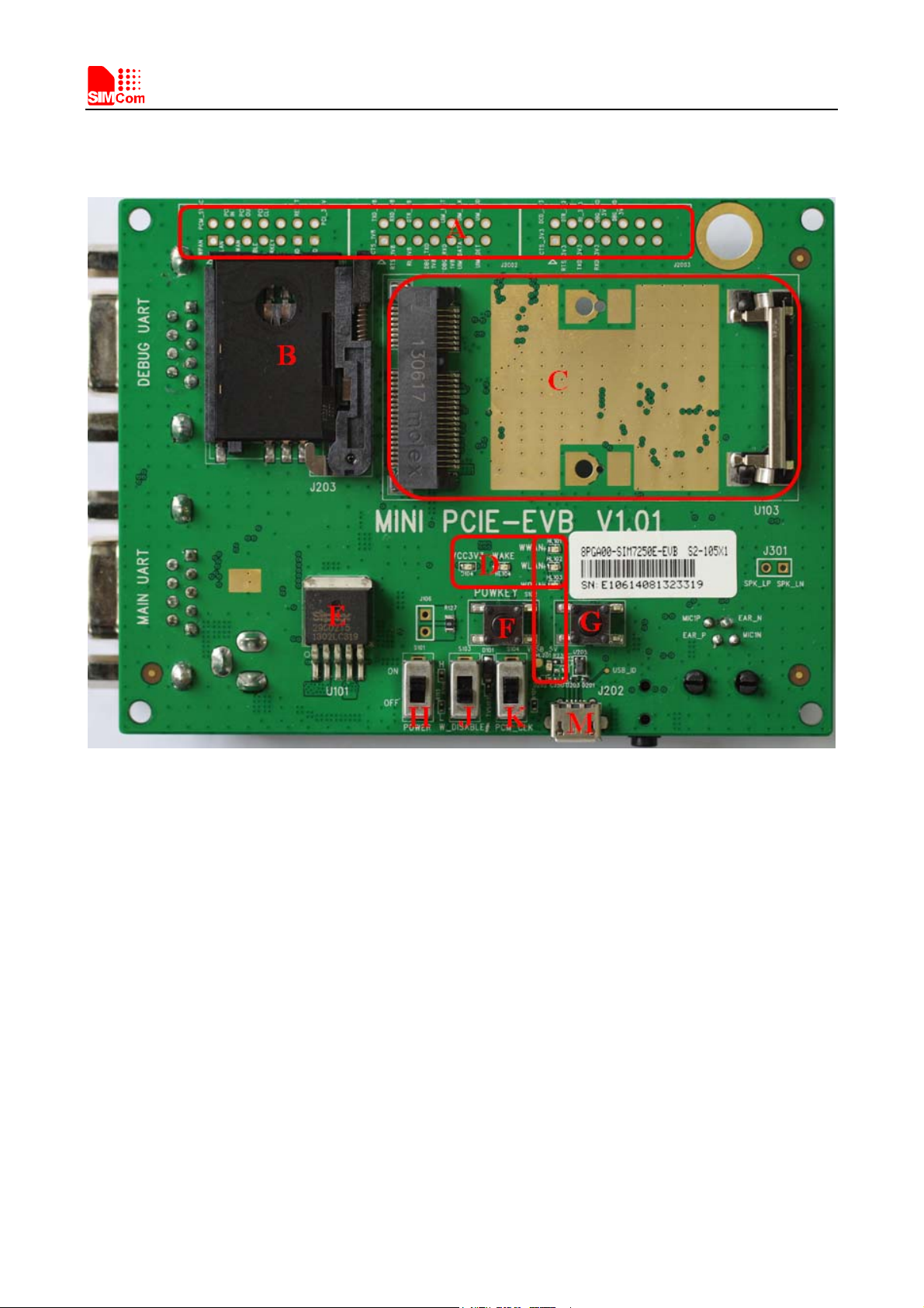
FIGURE 1: EVB TOP VIEW ............................................................................................................................................. 7
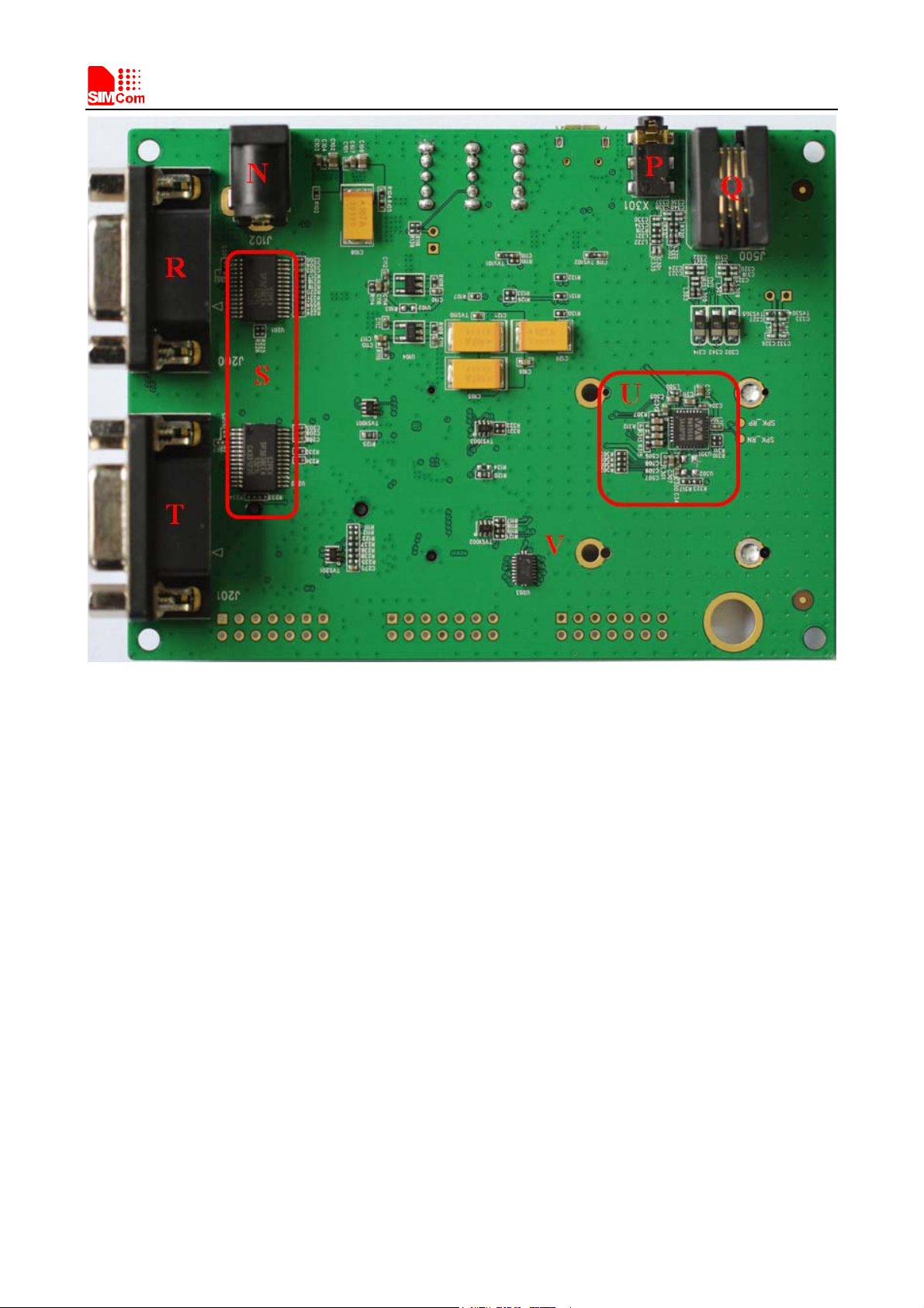
FIGURE 2: EVB BOTTOM VIEW.................................................................................................................................... 8
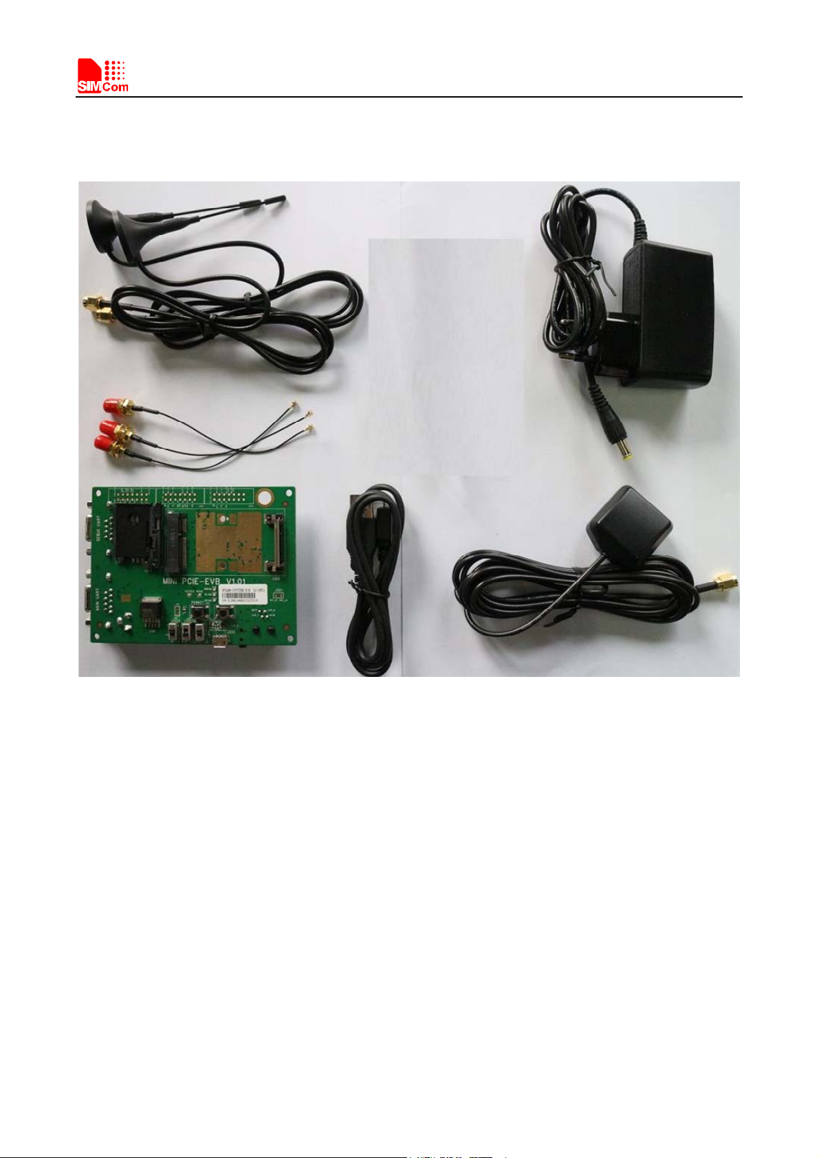
FIGURE 3: EVB ACCESSORY......................................................................................................................................... 9
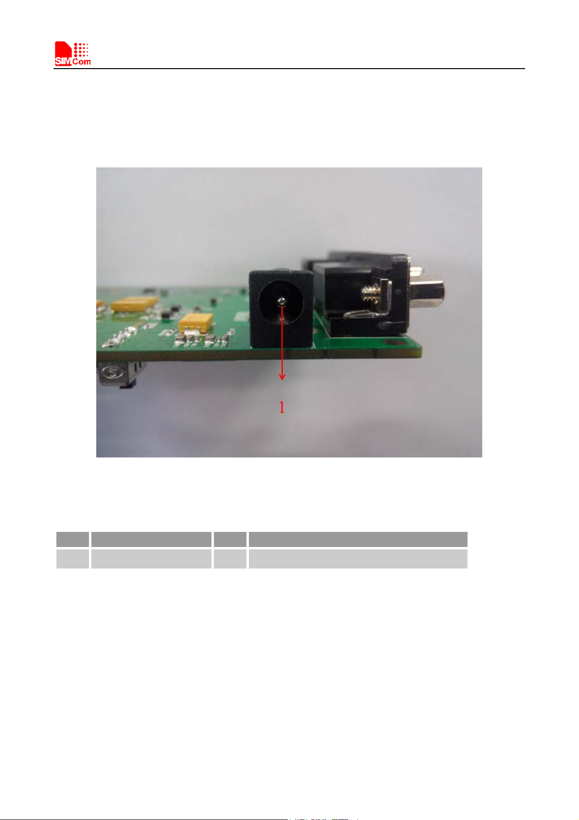
FIGURE 4: ADAPTER INTERFACE .............................................................................................................................. 10
FIGURE 5: AUDIO INTERFACE.................................................................................................................................... 11
FIGURE 6: SIM CARD INTERFACE ............................................................................................................................. 12
FIGURE 7: ANTENNA INTERFACE ............................................................................................................................. 13
FIGURE 8: UART PORTS ............................................................................................................................................... 14
FIGURE 9: LED INDICATOR AND SWITCH............................................................................................................... 15
FIGURE 10: TEST INTERFACE OVERVIEW ............................................................................................................... 17
FIGURE 11: J2001 INTERFACE..................................................................................................................................... 17
FIGURE 12: J2002 INTERFACE..................................................................................................................................... 18
FIGURE 13: J2003 INTERFACE..................................................................................................................................... 19
FIGURE 14: EVB AND ACCESSORY ........................................................................................................................... 20
FIGURE 15: COM PORTS AND MODEM..................................................................................................................... 21
FIGURE 16: RUN THE HYPER TERMINAL ................................................................................................................ 22
FIGURE 17: NAME THE HYPER TERMINAL ............................................................................................................. 22
FIGURE 18: CHOOSE THE RIGHT COM PORT .......................................................................................................... 23
FIGURE 19: SET UP THE COM PROPERTY ................................................................................................................ 24
FIGURE 20: CONNECT THE MODULE ....................................................................................................................... 24
FIGURE 21: MAKE A CALL .......................................................................................................................................... 25
FIGURE 22: OPEN GNSS ............................................................................................................................................... 25
FIGURE 23: RUN THE DOWNLOAD TOOL................................................................................................................ 26
FIGURE 24: BROWSE THE SOFTWARE PACKAGE .................................................................................................. 27
FIGURE 25: START DOWNLOAD ................................................................................................................................28
FIGURE 26: BACKUP QCN ........................................................................................................................................... 29
FIGURE 27: BACKUP FINISHED.................................................................................................................................. 29
FIGURE 28: DOWN FW ................................................................................................................................................. 30
FIGURE 29: DOWNLOADING IN PROCESS............................................................................................................... 30
FIGURE 30: DOWNLOADING IN PROCESS............................................................................................................... 31
FIGURE 31: RE ENUMERATION AND CONNECTION DEVICE .............................................................................. 31
FIGURE 32: RECOVER QCN......................................................................................................................................... 32
FIGURE 33: RECOVER QCN FINISHED...................................................................................................................... 32
FIGURE 34: DOWN AP .................................................................................................................................................. 33
FIGURE 35: DOWN AP FINISHED................................................................................................................................33
FIGURE 36: ISO UPGRADE .......................................................................................................................................... 34
FIGURE 37: PUSH FINISHED ....................................................................................................................................... 34

Smart Machine Smart Decision
Mini PCIe _EVBkit_UserGuide_V1.00 6 2014-05-05
Version History
Data Version Description of change Author
2014-05-05 1.00 Origin Honggang Ma
SCOPE
This document describes how to use Mini PCIe EVB to do test; user can get useful information about the Mini
PCIe EVB quickly through this document. This document applies to Mini PCIe products from SIMCom
Company.
This document is subject to change without notice at any time.

Smart Machine Smart Decision
1. Mini PCIe EVB
Figure 1: EVB top view
Mini PCIe _EVBkit_UserGuide_V1.00 7 2014-05-05

Smart Machine Smart Decision
Mini PCIe _EVBkit_UserGuide_V1.00 8 2014-05-05
Figure 2: EVB bottom view
A: Test point
B: SIM card socket with SIM_DET function
C: Mini PCIe card holder
D: Indicator LED
E: System power (3.3V)
F: Power on key (reserved)
G: System reset key
H: Power switch
J: RF control switch
K: WM8960 clock enable signal (reserved)
M: Micro USB connector
N: 5V DC jack
P: Audio jack (reserved)
Q: Handset jack
R: Main UART (reserved)
S: UART to RS232 IC
T: DBG UART (reserved)
U: WM8960 codec
V: Level shifter

Smart Machine Smart Decision
2. EVB Accessory
AB
C
DEF
Figure 3: EVB accessory
A: GSM/WCDMA/LTE Antenna
B: 5V DC adapter
C: Antenna cable
D: Mini PCIe EVB
E: Micro USB cable
F: GPS/GLONASS Antenna
Mini PCIe _EVBkit_UserGuide_V1.00 9 2014-05-05

Smart Machine Smart Decision
3. Accessory Interface
3.1 Adapter Interface
Figure 4: Adapter interface
Table 1: 5V adapter interface
Pin Signal I/O Description
1 Adapter input I5V/2.0A DC source input
Mini PCIe _EVBkit_UserGuide_V1.00 10 2014-05-05
Tabla de contenidos
Manuales populares de Hardware de computadora de otras marcas

EMC2
EMC2 VNX Series Manual del propietario

Panasonic
Panasonic DV0PM20105 Manual de usuario

Mitsubishi Electric
Mitsubishi Electric Q81BD-J61BT11 Manual de usuario

Gigabyte
Gigabyte B660M DS3H AX DDR4 Manual de usuario

Raidon
Raidon iT2300 Manual de usuario

National Instruments
National Instruments PXI-8186 Manual de usuario


