Sigfox WSSFCB-NH3 Manual de usuario

WSSFC- NH3-MN-EN-01
AUG-2021
SKU
WSSFCB-NH3
HW Ver.
1.1
FW Ver.
1.0
Item Code
WSSFCB-NH3-8-01
Wireless Sigfox Ammonia Gas Sensor with BLE, Internal antenna, Type AA battery 1.5VDC, IP67,
RC1 zone
WSSFCB-NH3-9-01
Wireless Sigfox Ammonia Gas Sensor with BLE, Internal antenna, Type AA battery 1.5VDC, IP67,
RC2-RC4 zones
STEP 1: Select RC
1. Select RC zone
RC zones selection 1, 2, 4,... is RCZ1, RCZ2, RCZ4,... (refer to section
6)
STEP 2: Check ID and PAC
Use Modbus Configuration Cable to read the ID and PAC values
Refer to register address 8 and 10 (DEC)
USER GUIDE FOR SIGFOX-READY
AMMONIA GAS SENSOR WITH BLE
WSSFCB-NH3
This document is applied for the following products
0. Configuration Check List

STEP 3: Configure the sensor's operating parameters
Configure parameters like cycle send data, alarm, a, b,...
Refer to the configuration section 5
STEP 4: Add device to Backend Sigfox
refer to section 5.2 for details
STEP 5: Installation
refer to section 8 for details
HW Ver.
FW Ver.
Release Date
Functions Change
1.1
1.0
DEC-2020
WSSFC-NH3 is a Sigfox-ready electrochemical-type gas sensor which has high sensitivity to low concentrations of
ammonia gas, high selectivity, and a stable baseline. Integrated ambient humidity and temperature so the sensor can
be measured by special algorithm expertise through modelling and compensating of external heat sources without the
need of any additional components. With Ultra-low power design and smart firmware allow the complete Wireless and
Sensor package run on 1 x AA battery 3.6V for 2-5 years with 15 minutes update. It can support all regions of Sigfox
network in over the World, RC1, RC2, & RC4.
Typical Applications: Monitor leakage of Ammonia gas for Refrigerator, monitor Ammonia in private or public
toilets,...
SENSORS SPECIFICATION:
NH3 sensor
electrochemical-type gas sensor
1. Functions Change Log
2. Introduction
3. Specification

Measuring range for NH3
0..100 ppm
Max detecting concentration
200 ppm
Repeatability / Resolution / Stability per month
< 10% of Reading value / 1 ppm / < 2% of Reading value
Zero stability
+/- 2 ppm
Working atmospheric pressure
101.3 Kpa +/- 10%
Sensor life
> 2 years
Humidity and Temperature sensor
Digital type, factory calibrated
Humidity measuring range / accuracy / resolution
0 .. 100 %RH, ± 2.0% / 0.1%
Temperature measuring range / accuracy / resolution
-40 .. + 85°C / ± 0.2°C / 0.1°C
Working temperature and humidity
-30 .. + 50°C, 15 .. 90% RH
Sensor housing / Rating
SS316/SS304 housing with 316SS sintered filter / for Indoor use
Sigfox SPECIFICATION:
Sigfox zones
select RC1-RC2-RC4
Antenna
Internal Antenna 2dbi
Battery
02 x AA Type 1.5VDC, working time up to 10 years (depends on
configuration)
RF Module complies to
CE, FCC, ARIB
Working temperature
-40°C..+60°C (using Energizer Lithium Ultimate AA battery)
Housing/Protection
Aluminum + Polycarbonate / IP67
Dimension / Net weight
H180xW73xD42 / < 400 grams
4. Dimensions
5. Operation Principle

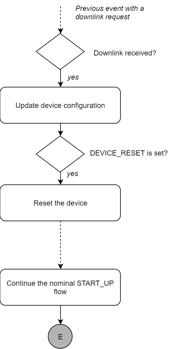
After 1 minute 30 seconds later the device will send the first data packet and at the same time wait for the downlink
packet from the Base Station.
Then during the operation, there are 03 cases of sending data to base station:
1. When the sensor sampling time interval is reached, the Sigfox node will read the data from Input or sensor
and performing the calculation. After that it will check calculated value with alarm thresholds. If the calculated
was out off the threshold values (Lo or Hi), called alarm, and the number of times of alarm did not pass the limit
of number of alarms, then it will send data to Base station immediately;
2. When the sending time interval is reached, it will send data to Base station immediately, regardless of value;
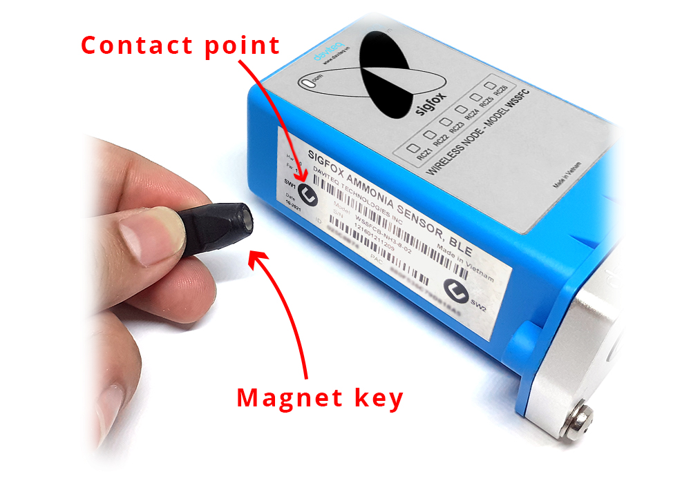
3. By using the magnet key, the Sigfox node can be triggered to send data to base station immediately. There
will be a beep sound from the buzzer meaning the data has been sent.
REED SWITCH
EVENT
PRE-
CONDITION
ACTION
LED STATUS
BUZZER
STATUS
ACTIVITIES
POST-
CONDITION
2
START_UP
Any state
Move Magnet
Key to contact
point of REED
SWITCH and
hold 5s.
Buzzer beep 1
long time.
Blink WHITE
Beep 1 long
time
See FW specs
Device reset
1
FORCE_DATA
Any state
Move Magnet
Key to contact
point of REED
SWITCH.
Buzzer beeps 1
time, move
Magnet Key
away.
Blink SKY
BLUE
Beep 1 time
See FW specs
Back to
previous state
1
PARAMETERS_UPDATE
Any state
Move Magnet
Key to contact
point of REED
SWITCH.
Buzzer beeps 1
time, hold
Magnet Key 5s.
Buzzer beeps 2
times.
Blink PURPLE
Beep 2 times
See FW specs
Back to
previous state
Upon power on, the Sigfox node has 60 seconds to wait for off-line configuration (via cable with ModbusRTU
protocol)
NOTE:
Once sending the data to base station by this alarm event, the timer of sending time interval will be reset;
NOTE:
Once sending the data to base station by the magnet key, the timer of sending time interval will be reset;
The shortest time interval between the two manual triggers is 5s. if shorter than 5s, there will be no data
sending.

The RF transmit power will be automatically set as the max value as allowed by the Zone.
Sigfox Radio Configuration (RC) defines the radio parameters in which the device shall operate: Sigfox operating
frequencies, output power, spectrum access mechanism, throughput, coexistence with other radio technologies, etc.
Each radio configuration includes 4 uplink classes: 0u, 1u, 2u, and 3u.
The Sigfox network globally works within the ranges from 862 to 928 MHz. But not all RCs require such a wide range of
operation.
RC1
RC2
RC3
RC4
RC5
RC6
RC7
Uplink center frequency
(MHz)
868.130
902.200
923.200
920.800
923.300
865.200
868.800
Downlink center
frequency (MHz)
869.525
905.200
922.200
922.300
922.300
866.300
869.100
Uplink data rate (bit/s)
100
600
100
600
100
100
100
Downlink data rate (bit/s)
600
600
600
600
600
600
600
Sigfox recommended
EIRP (dBm)
16
24
16
24
14
16
16
Specifics
Duty cycle
1% *
Frequency
hopping **
Listen Before
Talk ***
Frequency
hopping **
Listen Before
Talk ***
Duty cycle
1% *
* Duty cycle is 1% of the time per hour (36 seconds). For an 8 to 12 bytes payload, this means 6 messages per hour,
140 per day.
** Frequency hopping: The device broadcasts each message 3 times on 3 different frequencies. Maximum On time
400 ms per channel. No new emission before 20 s.
*** Listen Before Talk: Devices must verify that the Sigfox-operated 200 kHz channel is free of any signal stronger
than −80 dBm before transmitting.
Sigfox’s high limit EIRP recommendation is included in each column although regulations sometimes allow for more
radiated power than the Sigfox recommendation.
Sigfox’s recommendation is set to comply with the Sigfox technological approach of:
Low current consumption
Balanced link budget between uplink and downlink communication
5.1 RC technical details

EVENT_TYPE
START_UP event is prepared every time the device is starting up. It can be either if the device is starting for the first
time, or when the device is being reset. The device can be reset by two possible ways, one is thanks to the reed power
switch , the other thanks to the DEVICE_RESET flag set in a downlink message.
Nominal flow:
5.3 Device behavior & Firmware Specification of
NH3 Sensor
Please read
sections 5.5
to 5.8 carefully for a better understanding of the configuration
5.3.1 Start-up features
5.3.1.1 Payload fields
5.3.1.2 Description
5.3.1.3 Frame
5.3.1.4 Flowchart

HEARTBEAT_PERIOD
EVENT_TYPE
HW_VERSION
FW_VERSION
LATEST_SIGFOX_DOWNLINK
HEARTBEAT event is prepared every HEARTBEAT_PERIOD. When the uplink message of the HEARTBEAT event is
prepared, the latest valid configuration that the device has received is provided through the
LATEST_SIGFOX_DOWNLINK field.
The HEARTBEAT event is a Sigfox downlink exchange. Thanks to the downlink message, pre-defined parameters of the
device can be modified in order to change the device behavior.
5.3.2 Heartbeat feature
5.3.2.1 Parameters
5.3.2.2 Payload fields
5.3.2.3 Description
5.3.2.4 Frame
Este manual sirve para los siguientes modelos
2
Tabla de contenidos
Otros manuales de Accesorios de Sigfox


