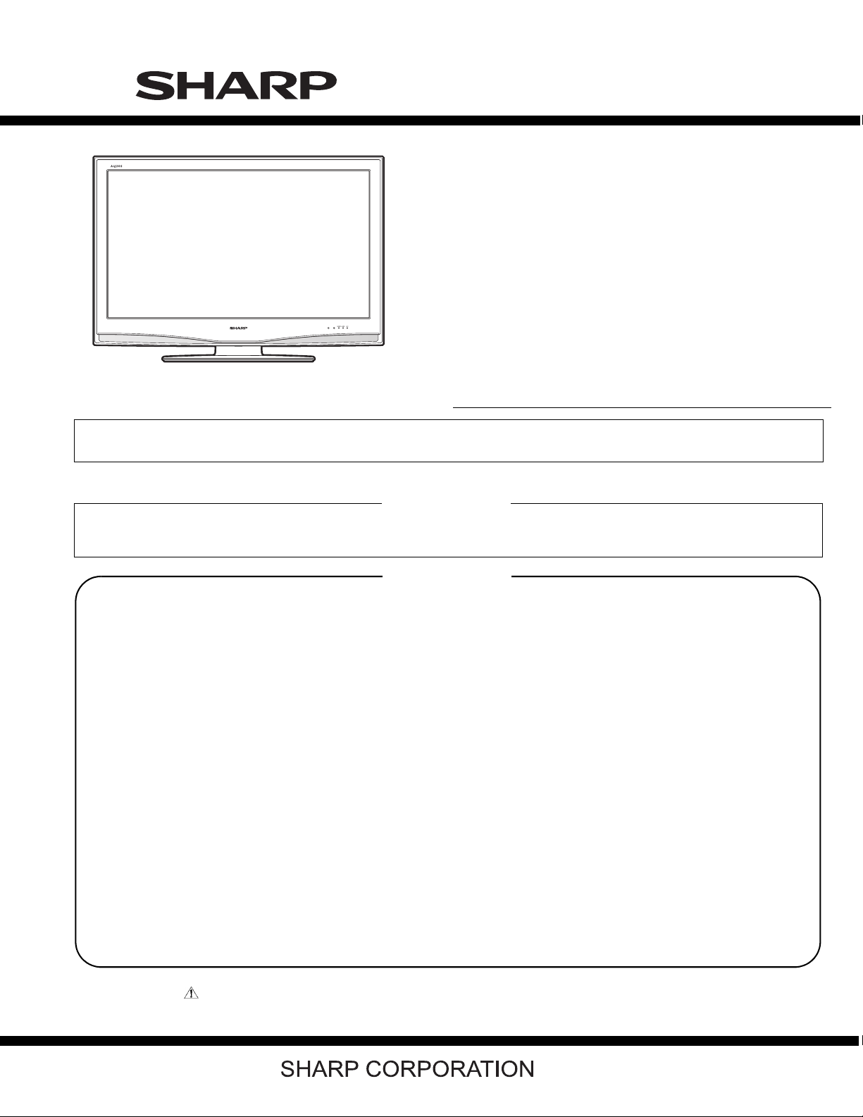
Sharp AQUOS LC-46D43U Manual de usuario

SERVICE MANUAL
LC-42D43U
No.S77L5LC42D43U
LCD COLOR TELEVISION
LC-42D43U
MODEL
Parts marked with " " are important for maintaining the safety of the set. Be sure to replace these parts with specified ones for maintaining the
safety and performance of the set.
This document has been published to be used for
after sales service only.
The contents are subject to change without notice.
OUTLINE AND MODIFIED PARTS LIST
OUTLINE.............................................................i
MODIFIED PARTS LIST .....................................i
SAFETY PRECAUTION
IMPORTANT SERVICE SAFETY PRE-
CAUTION ..........................................................iv
PRECAUTIONS A PRENDRE LORS DE
LA REPARATION ...............................................v
CHAPTER 1. OPERATION MANUAL
[1] SPECIFICATIONS ......................................... 1-1
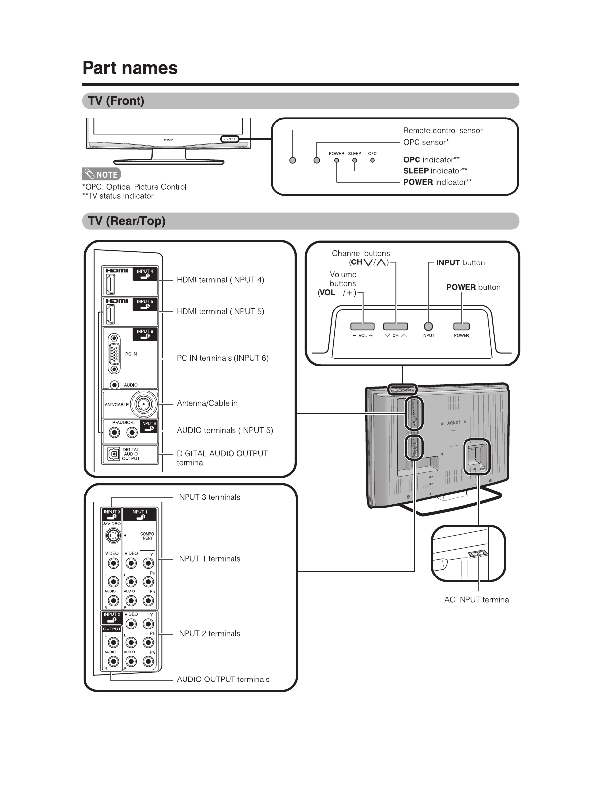
[2] OPERATION MANUAL .................................. 1-2
[3] DIMENSIONS ................................................ 1-8
CHAPTER 2. REMOVING OF MAJOR PARTS
[1] REMOVING OF MAJOR PARTS ................... 2-1
CHAPTER 3. ADJUSTMENT
[1] ADJUSTMENT PROCEDURE ....................... 3-1
CHAPTER 4. TROUBLESHOOTING TABLE
[1] TROUBLESHOOTING TABLE ......................4-1
CHAPTER 5. OVERALL WIRING DIAGRAM/BLOCK
DIAGRAM
[1] OVERALL WIRING DIAGRAM ......................5-1
[2] SYSTEM BLOCK DIAGRAM.........................5-3
CHAPTER 6. PRINTED WIRING BOARD
[1] AV TERMINAL UNIT PRINTED WIRING
BOARD..........................................................6-1
CHAPTER 7. SCHEMATIC DIAGRAM
[1] DESCRIPTION OF SCHEMATIC DIA-
GRAM............................................................7-1
[2] SCHEMATIC DIAGRAM ................................7-2
Parts Guide
TopPage
CONTENTS
In the interests of user-safety (Required by safety regulations in some countries) the set should be restored to its orig-
inal condition and only parts identical to those specified should be used.
In the interests of user-safety (Required by safety regulations in some countries) the set should be restored to its orig-
inal condition and only parts identical to those specified should be used.
This Service Manual covers the differences from LC-32/37D42U. For other technical information, refer to the LC-
32/37D42U (No. S06X9LC32D42U) Service Manual.
OUTLINE
SUPPLEMENT ATTACHED

LC-42D43U
i
LC-42D43U Service Manual
OUTLINE AND MODIFIED PARTS LIST
OUTLINE
This Service Manual covers the differences from LC-32/37D42U. For other technical information, refer to the LC-32/37D42U (No. S06X9LC32D42U)
Service Manual.
MODIFIED PARTS LIST
Ref.No. Description LC-32D42U/37D42U
(Base Model)
LC-42D43U Remark
PRINTED WIRING BOARD ASSEMBLIES
R/C, LED Unit DUNTKD909FM02 DUNTKD909FM02 No Change
KEY Unit DUNTKD910FM02 DUNTKD910FM02 No Change
AV TERMINAL Unit DUNTKD999FM04 DUNTKD935FM03 Change
MAIN Unit DUNTKD862FM04 DUNTKD862FM04 Change
POWER Unit RDENCA198WJQZ RDENCA266WJQZ Unit Replacement Item
LCD PANEL (NOTE: THE PARTS HERE SHOWN ARE SUPPLIED AS AN ASSEMBLY BUT NOT INDEPENDENTLY.)
32" LCD Panel R1LK315T3LZ4BX - Delete
37" LCD Panel R1LK370T3LZ5BW - Delete
42" LCD Panel - RLCUCA122WJZZ Add.
MAIN Unit
C1118 Capacitor 10 16V Ceramic RC-KZA510WJPZY RC-KZA237WJZZY Change
C1311 Capacitor 10 16V Ceramic RC-KZA510WJPZY RC-KZA237WJZZY Change
C1313 Capacitor 10 16V Ceramic RC-KZA510WJPZY RC-KZA237WJZZY Change
C1403 Capacitor 10 16V Ceramic RC-KZA510WJPZY RC-KZA237WJZZY Change
C1423 Capacitor 10 16V Ceramic RC-KZA510WJPZY RC-KZA237WJZZY Change
C1426 Capacitor 10 16V Ceramic RC-KZA510WJPZY RC-KZA237WJZZY Change
C1433 Capacitor 10 16V Ceramic RC-KZA510WJPZY RC-KZA237WJZZY Change
C1437 Capacitor 10 16V Ceramic RC-KZA510WJPZY RC-KZA237WJZZY Change
C1466 Capacitor 10 16V Ceramic RC-KZA510WJPZY RC-KZA237WJZZY Change
C1467 Capacitor 10 16V Ceramic RC-KZA510WJPZY RC-KZA237WJZZY Change
C1531 VCKYCZ1EF104ZY - Delete
C1536 RC-KZA115WJZZY - Delete
C2001 Capacitor 10 16V Ceramic RC-KZA510WJPZY RC-KZA237WJZZY Change
D1303 Diode KDS4148U-RTK/P VHD1SS355//-1Y VHDKDS4148/-1Y Change
D1311 Diode PDZ9.1B,115 RH-EXA485WJQZY RH-EX0264TAZZY Change
D1519 VHDRB521S30-1Y - Delete
D2003 RH-PXA018WJZZY - Delete
D8451 Diode KDS4148U-RTK/P VHD1SS355//-1Y VHDKDS4148/-1Y Change
D9602 Zener Diode EX0256TA RH-EXA089WJZZY RH-EX0256TAZZY Change
D9606 Diode KDS4148U-RTK/P VHD1SS352//-1Y VHDKDS4148/-1Y Change
D9607 Zener Diode EX0256TA RH-EXA089WJZZY RH-EX0256TAZZY Change
D9701 Diode KDS4148U-RTK/P VHD1SS352//-1Y VHDKDS4148/-1Y Change
D9702 Diode KDS4148U-RTK/P VHD1SS352//-1Y VHDKDS4148/-1Y Change
D9703 Diode PDZ3.3B,115 - RH-EX0253TAZZY Add.
FB2604 Balun BLN-A206WJ RBLN-0207TAZZY RBLN-A206WJZZY Change
FB9701 Balun BLN-0236TA RBLN-0237TAZZY RBLN-0236TAZZY Change
IC1503 IC LVC2G14G-1 VHiN74LVC14-1Y VHiLVC2G14G-1Y Change
IC1504 VHiT7WH123U-1Y - Delete
IC2003 IC HC2G66DP-1 VHiTC7W66U/-1Y VHiHC2G66DP-1Y Change
IC2006 IC AHC32PW VHiTCVHC32T-1Y VHiAHC32PW+-1Y Change
IC3302 IC TAR5SB25 VHiPQ1X251M-1Y VHiTAR5SB25-1Y Change
IC3304 IC S29GL064A90TFIR20H VHiMST3586M-1Q VHiMST3583M-1Q Change
IC8701 IC TAR5SB33-1 VHiPQ1X331M-1Y VHiTAR5SB33-1Y Change
P1401 QPLGN0055CEZZY - Delete
P2001 QPLGN0060CEZZY - Delete
P2601 Plug QPLGNA522WJQZY QPLGNA493WJZZY Change
P8401 QPLGN0060CEZZY - Delete
P9101 QPLGN0060CEZZY - Delete
P9202 QPLGNA144WJZZY - Delete
P9301 QCNCWA562WJQZY - Delete
Q1524 Transistor RT1N141U-T111-1 - VSRT1N141U/-1Y Add.
Q1525 Transistor KTA1535T-RTK/P - VSKTA1535T+-1Y Add.
Q2001 VSKRC404E++-1Y - Delete

LC-42D43U
ii
Q8452 Transistor KTA1298Y VS2SA1362GR-1Y VSKTA1298Y+-1Y Add.
R1170 VRS-CZ1JF000JY - Delete
R1176 VRS-CZ1JF000JY - Delete
R1401 VRS-CJ1JF101JY - Delete
R1402 VRS-CZ1JF101JY - Delete
R1403 VRS-CZ1JF000JY - Delete
R1412 VRS-CZ1JF000JY - Delete
R1511 VRS-CZ1JF330JY - Delete
R1513 VRS-CZ1JF102FY - Delete
R1521 VRS-CZ1JF000JY - Delete
R1522 VRS-CZ1JF223FY - Delete
R1523 VRS-CZ1JF101JY - Delete
R1524 VRS-CZ1JF103FY - Delete
R1531 VRS-CZ1JF330JY - Delete
R1597 Resistor 10k 1/16W Metal Oxide - VRS-CZ1JF103FY Add.
R1599 Resistor 330 1/16W Metal Oxide - VRS-CZ1JF331JY Add.
R1609 VRS-CZ1JF472JY - Delete
R1614 VRS-CZ1JF472JY - Delete
R2012 VRS-CZ1JF000JY - Delete
R2013 VRS-CZ1JF000JY - Delete
R2017 VRS-CZ1JF000JY - Delete
R2030 VRS-CZ1JF000JY - Delete
R2039 VRS-CZ1JF000JY - Delete
R2040 VRS-CZ1JF000JY - Delete
R2041 VRS-CZ1JF152JY - Delete
R2069 Resistor 4.7k 1/16W Metal Oxide - VRS-CZ1JF472JY Add.
R2254 VRS-CZ1JF000JY - Delete
R2255 VRS-CZ1JF000JY - Delete
R2256 VRS-CZ1JF000JY - Delete
R2259 VRS-CZ1JF000JY - Delete
R2261 VRS-CZ1JF000JY - Delete
R2263 VRS-CZ1JF000JY - Delete
R2264 VRS-CZ1JF000JY - Delete
R2629 Resistor 0 1/16W Metal Oxide VRK-CD1JJ000JY VRS-CK1JJ000JY Change
R2630 Resistor 0 1/16W Metal Oxide VRK-CD1JJ000JY VRS-CK1JJ000JY Change
R2631 Resistor 0 1/16W Metal Oxide VRK-CD1JJ000JY VRS-CK1JJ000JY Change
R3307 VRS-CZ1JF000JY - Delete
R3323 VRS-CZ1JF000JY - Delete
R3324 VRS-CZ1JF000JY - Delete
R8144 Resistor 47 1/16W Metal Oxide VRK-CD1JJ470JY VRS-CK1JJ470JY Change
R8162 Resistor 47 1/16W Metal Oxide VRK-CD1JJ470JY VRS-CK1JJ470JY Change
R8163 Resistor 47 1/16W Metal Oxide VRK-CD1JJ470JY VRS-CK1JJ470JY Change
R8164 Resistor 47 1/16W Metal Oxide VRK-CD1JJ470JY VRS-CK1JJ470JY Change
R8169 Resistor 47 1/16W Metal Oxide VRK-CD1JJ470JY VRS-CK1JJ470JY Change
R8170 Resistor 47 1/16W Metal Oxide VRK-CD1JJ470JY VRS-CK1JJ470JY Change
R8197 Resistor 47 1/16W Metal Oxide VRK-CD1JJ470JY VRS-CK1JJ470JY Change
R8198 Resistor 47 1/16W Metal Oxide VRK-CD1JJ470JY VRS-CK1JJ470JY Change
R8199 Resistor 47 1/16W Metal Oxide VRK-CD1JJ470JY VRS-CK1JJ470JY Change
R8454 VRK-CD1JJ000JY - Delete
R8455 VRK-CD1JJ000JY - Delete
R8701 VRK-CD1JJ000JY - Delete
R8702 VRS-CH1JF000JY - Delete
R8709 VRS-CH1JF000JY - Delete
R8729 VRS-CZ1JF000JY - Delete
R9007 Resistor 4.7k 1/16W Metal Oxide - VRS-CZ1JF472JY Add.
R9116 VRK-CD1JJ000JY - Delete
R9201 VRS-CZ1JF470JY - Delete
R9205 VRS-CZ1JF000JY - Delete
R9209 VRS-CZ1JF470JY - Delete
R9306 VRS-CZ1JF103JY - Delete
R9614 VRS-CZ1JF100JY - Delete
R9712 Resistor 3.9k 1/16W Metal Oxide VRS-CZ1JF183FY VRS-CZ1JF392JY Change
R9713 VRS-CZ1JF333JY - Delete
SC1503 Socket QSOCNA101WJN1 QSOCNA004WJZZ Change
Ref.No. Description LC-32D42U/37D42U
(Base Model)
LC-42D43U Remark

LC-42D43U
iii
TU1101 Tuner RTUDAA007WJQZ RTUDAA018WJQZ Change
AV TERMINAL Unit
Refer to Parts List.
CABINET PARTS
Refer to Parts List.
SUPPLIED ACCESSORIES
Refer to Parts List.
PACKING PARTS
Refer to Parts List.
SERVICE JIGS
Refer to Parts List
Ref.No. Description LC-32D42U/37D42U
(Base Model)
LC-42D43U Remark

LC-42D43U
iv
LC-42D43U Service Manual
SAFETY PRECAUTION
IMPORTANT SERVICE SAFETY PRECAUTION
WARNING
1. For continued safety, no modification of any circuit should be
attempted.
2. Disconnect AC power before servicing.
BEFORE RETURNING THE RECEIVER (Fire &
Shock Hazard)
Before returning the receiver to the user, perform the following
safety checks:
3. Inspect all lead dress to make certain that leads are not pinched,
and check that hardware is not lodged between the chassis and
other metal parts in the receiver.
4. Inspect all protective devices such as non-metallic control knobs,
insulation materials, cabinet backs, adjustment and compartment
covers or shields, isolation resistor-capacitor networks, mechanical
insulators, etc.
5. To be sure that no shock hazard exists, check for leakage current in
the following manner.
• Plug the AC cord directly into a 120 volt AC outlet.
• Using two clip leads, connect a 1.5k ohm, 10 watt resistor paral-
leled by a 0.15μF capacitor in series with all exposed metal cabinet
parts and a known earth ground, such as electrical conduit or elec-
trical ground connected to an earth ground.
• Use an AC voltmeter having with 5000 ohm per volt, or higher, sen-
sitivity or measure the AC voltage drop across the resistor.
• Connect the resistor connection to all exposed metal parts having a
return to the chassis (antenna, metal cabinet, screw heads, knobs
and control shafts, escutcheon, etc.) and measure the AC voltage
drop across the resistor.
All checks must be repeated with the AC cord plug connection
reversed. (If necessary, a nonpolarized adaptor plug must be used
only for the purpose of completing these checks.)
Any reading of 0.75 Vrms (this corresponds to 0.5 mA rms AC.) or
more is excessive and indicates a potential shock hazard which
must be corrected before returning the monitor to the owner.
///////////////////////////////////////////////////////////////////////////////////////////////////////////////////////////////////////////////////////////////////////////////////////////////////////////////////////////////////////////
SAFETY NOTICE
Many electrical and mechanical parts in LCD color television have
special safety-related characteristics.
These characteristics are often not evident from visual inspection, nor
can protection afforded by them be necessarily increased by using
replacement components rated for higher voltage, wattage, etc.
Replacement parts which have these special safety characteristics are
identified in this manual; electrical components having such features
are identified by " " and shaded areas in the Replacement Parts
List and Schematic Diagrams.
For continued protection, replacement parts must be identical to those
used in the original circuit.
The use of a substitute replacement parts which do not have the same
safety characteristics as the factory recommended replacement parts
shown in this service manual, may create shock, fire or other hazards.
///////////////////////////////////////////////////////////////////////////////////////////////////////////////////////////////////////////////////////////////////////////////////////////////////////////////////////////////////////////
Service work should be performed only by qualified service technicians who are thoroughly familiar with all safety checks and the
servicing guidelines which follow:
CAUTION: FOR CONTINUED PROTECTION
AGAINST A RISK OF FIRE REPLACE ONLY WITH
SAME TYPE FUSE.
F701 (250V 8A)
DVM
AC SCALE
1.5k ohm
10W
TO EXPOSED
METAL PARTS
CONNECT TO
KNOWN EARTH
GROUND
0.15
μ
F
TEST PROBE

LC-42D43U
v
PRECAUTIONS A PRENDRE LORS DE LA REPARATION
De nombreuses pièces, électriques et mécaniques, dans les télévi-
seur ACL présentent des caractéristiques spéciales relatives à la sé-
curité, qui ne sont souvent pas évidentes à vue. Le degré de protec-
tion ne peut pas être nécessairement augmentée en utilisant des
pièces de remplacement étalonnées pour haute tension, puissance,
etc.
Les pièces de remplacement qui présentent ces caractéristiques sont
identifiées dans ce manuel; les pièces électriques qui présentent ces
particularités sont identifiées par la marque " " et hachurées dans la
liste des pièces de remplacement et les diagrammes schématiques.
Pour assurer la protection, ces pièces doivent être identiques à celles
utilisées dans le circuit d'origine. L'utilisation de pièces qui n'ont pas
les mêmes caractéristiques que les pièces recommandées par l'usine,
indiquées dans ce manuel, peut provoquer des électrocutions, incen-
dies, radiations X ou autres accidents.
AVERTISSEMENT
1.
2.
3.
4.
5.
•
•
•
•
/////////////////////////////////////////////////////////////////////////////////////////////////////////////////////////////////////////////////////////////////////////////////////////////////////////////////////////////////////////////
/////////////////////////////////////////////////////////////////////////////////////////////////////////////////////////////////////////////////////////////////////////////////////////////////////////////////////////////////////////////
Ne peut effectuer la réparation qu' un technicien spécialisé qui s'est parfaitement accoutumé à toute vérification de sécurité et aux
conseils suivants.
N'entreprendre aucune modification de tout circuit. C'est danger-
eux.
Débrancher le récepteur avant toute réparation.
Inspecter tous les faisceaux de câbles pour s'assurer que les fils
ne soient pas pincés ou qu'un outil ne soit pas placé entre le châs-
sis et les autres pièces métalliques du récepteur.
Inspecter tous les dispositifs de protection comme les boutons de
commande non-métalliques, les isolants, le dos du coffret, les cou-
vercles ou blindages de réglage et de compartiment, les réseaux
de résistancecapacité, les isolateurs mécaniques, etc.
S'assurer qu'il n'y ait pas de danger d'électrocution en vérifiant la
fuite de courant, de la facon suivante:
Brancher le cordon d'alimentation directem-ent à une prise de cou-
rant de 120V. (Ne pas utiliser de transformateur d'isolation pour
cet essai).
A l'aide de deux fils à pinces, brancher une résistance de 1.5 kΩ
10 watts en parallèle avec un condensateur de 0.15μF en série
avec toutes les pièces métalliques exposées du coffret et une terre
connue comme une conduite électrique ou une prise de terre
branchée à la terre.
Utiliser un voltmètre CA d'une sensibilité d'au moins 5000Ω/V pour
mesurer la chute de tension en travers de la résistance.
Toucher avec la sonde d'essai les pièces métalliques exposées qui
présentent une voie de retour au châssis (antenne, coffret métalli-
que, tête des vis, arbres de commande et des boutons, écusson,
etc.) et mesurer la chute de tension CA en-travers de la résistance.
Toutes les vérifications doivent être refaites après avoir inversé la
fiche du cordon d'alimentation. (Si nécessaire, une prise
d'adpatation non polarisée peut être utilisée dans le but de termin-
er ces vérifications.)
La tension de pointe mesurèe ne doit pas dépasser 0.75V (corre-
spondante au courant CA de pointe de 0.5mA).
Dans le cas contraire, il y a une possibilité de choc électrique qui
doit être supprimée avant de rendre le récepteur au client.
PRECAUTION: POUR LA PROTECTION CON-
TINUE CONTRE LES RISQUES D'INCENDIE,
REMPLACER LE FUSIBLE
F701 (250V 8A)
VERIFICATIONS CONTRE L'INCEN-DIE ET LE
CHOC ELECTRIQUE
Avant de rendre le récepteur à l'utilisateur, effectuer les vérifica-
tions suivantes.
DVM
ECHELLE CA
1.5k ohm
10W
0.15
μ
F
SONDE D'ESSAI
AUX PIECES
METALLIQUES
EXPOSEES
BRANCHER A UNE
TERRE CONNUE
AVIS POUR LA SECURITE

LC-42D43U
1 – 1
LC-42D43U Service Manual
CHAPTER 1. OPERATION MANUAL
[1] SPECIFICATIONS

LC-42D43U
1 – 2
[2] OPERATION MANUAL

LC-42D43U
1 – 3

LC-42D43U
1 – 4
Otros manuales para AQUOS LC-46D43U
3
Este manual sirve para los siguientes modelos
1
Tabla de contenidos
Otros manuales de Televisor de pantalla plana de Sharp

Sharp
Sharp LC42D65U - LC - 42" LCD TV Manual de usuario

Sharp
Sharp LC-90LE657U Manual de usuario

Sharp
Sharp Aquos LC-32D47UA Manual de usuario

Sharp
Sharp LC-C5262U Manual de usuario

Sharp
Sharp Aquos LC-70LE845U Manual de usuario

Sharp
Sharp AQUOS LC-46D43U Manual de usuario

Sharp
Sharp LCD Modules for Industrial Appliance Manual de usuario

Sharp
Sharp Aquos LC C4067U Manual de usuario

Sharp
Sharp LC32SB27U - LC - 32" LCD TV Manual de usuario

Sharp
Sharp AQUOS LC-19D45U Manual de usuario