PS98i/PS9800 INSTRUCTIONS
Seametrics • 253.872.0284 Page 7 seametrics.com
INSTALLATION
Installing the Sensor
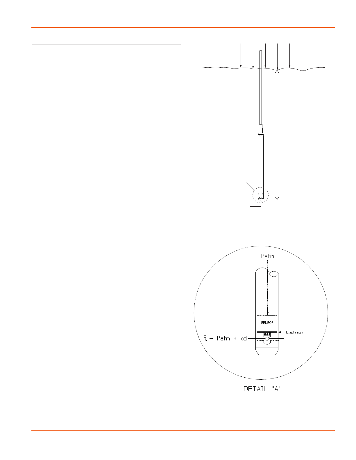
The PS98i/PS9800 measures pressure. The most common
application is measuring liquid levels in wells and tanks.
In order to do this, the sensor must be installed below
the water level at a xed depth. The installation depth
depends on the range of the sensor. One (1) PSI is equal to
approximately 2.31 feet of water. If you have a 5 PSI sensor,
the range is 11.55 feet of water and the sensor should not
be installed at a depth below 11.55 feet. If the sensor is
installed below its maximum range, damage may result to
the sensor and the output reading will not be correct.
• Lower the sensor to the desired depth.
• Fasten the cable to the well head using a weather
proof strain-relief system. When securing a vented
cable, make sure not to pinch the cable too tightly
or the vent tube inside the cable jacket may be
sealed o.
• Take a measurement to insure the sensor is not
installed below its maximum range.
• It is recommended that several readings be taken to
ensure proper operation after installation.
If a gauge unit is to be left in the well for a long-term
monitoring application, a desiccant tube must be installed
to prevent condensation in the cable vent tube. Water in
the vent tube will case inaccurate readings and, in time, will
work its way into the transmitter and damage it.
The sensor can be installed in any position; however, when
it leaves the factory it is calibrated in the vertical position.
Strapping the sensor body with tie wraps or tape will not
hurt it. Seametrics can provide an optional 1/4” NPT input
adapter which is interchangeable with the standard end
cone for those applications where it is necessary to directly
attach the sensor to a pipe, tank, or other pipe port. If the
sensor is being installed in a uid environment other than
water, be sure to check the compatibility of the uid with
the wetted parts of the sensor.
Cable Wiring
PS98i
Pressure PS9800
Pressure PS9800
Pressure & Tempturature
Shield Ground Ground Ground
White V+ V+ V+ (pressure)
Blue Signal return Signal return Signal return (pressure)
Yellow -- -- V+ (temperature)
Purple -- -- Signal return (temperature)
Desiccant Use
On vented sensors a desiccant tube prevents moisture in
the air from being sucked into the vent tube, which can
cause erratic readings and sensor damage.
The desiccant tube is lled with blue silica gel beads. A
locking barb and a hydrophobic water lter are attached to
the end of the desiccant tube. This lter prolongs the life of
the desiccant as much as three times over a desiccant tube
without the lter.
Install the sensor so that the desiccant tube will not ood
or lie in water.
The desiccant is a bright blue color when active and dry. See
Maintenance section for care and changing of desiccant.
Grounding Issues
It is commonly known that when using electronic
equipment, both personnel and equipment need to be
protected from high power spikes that may be caused by
lightning, power line surges, or faulty equipment. Without
a proper grounding system, a power spike will nd the path
of least resistance to earth ground—whether that path is
through sensitive electronic equipment or the person
operating the equipment. In order to ensure safety and
prevent equipment damage, a grounding system must be
used to provide a low resistance path to ground.
When using several pieces of interconnected equipment,
each of which may have its own ground, problems with
noise, signal interference, and erroneous readings may be
noted. This is caused by a condition known as a Ground
Loop. Because of natural resistance in the earth between
the grounding points, current can ow between the points,
creating an unexpected voltage dierence and resulting
erroneous readings.
The single most important step in minimizing a ground
loop is to tie all equipment (sensors, data loggers, external
power sources, and any other associated equipment)
to a single common grounding point. Seametrics
recommends connecting the shield to ground at the
top end. This is especially important in a pumping well
to avoid failure.