SEAKEY P1703-141 Manual de usuario
Installation Manual
User Guide
Reference Manual
Troubleshooting Guide
© Seakey AB

3
Contents
Installation manual – p. 4
1. Creating the user account
2. Installing the system
3. System start-up
4. Finishing the setup
5. Configuring system
User Guide – p. 15
• Systemmode
• Alarms
• Warnings
• ActivateandDeactivateAlarms
• Triggeredalarms
• Triggeredwarnings
Reference manual – p. 23
• Text(SMS)commands
• Installationtestmode
• Rebootaunit
• Power-cycleaunit
• Winterstorage/Shutdownunit
• Activationbuttonashes
Troubleshooting guide – p. 28
• Communicationrelatedproblems
• GPSrelatedproblems
• Alarmlooprelatedproblems
• Powerrelatedproblems
• Messagingandnoticationproblems
• Webportalproblems
SMS
WWW
WWW

4
Installation Manual
1. Creating the user account
Createyourpersonalwebportalaccountonwww.mycpod.combysending
theregistrationtextmessage,logginginandcompletingthesetupwizard.
a. Send registration text (SMS)
message
Sendatext(SMS)messagecontain-
ingtheactivationcodeofyourC-pod
unittotheC-podSystemNumber.
Theactivationcodeisprintedonthe
labelonyourC-podmainunit.Ithas
theformat1703200-XX-XXXXX-XX;
allhyphensmustbeincluded,no
othercharacterscanbeadded.
C-pod System Number
Storethesenumbersinyourphone!
International:
+ 4 67374 9 4 0 9 0
UnitedStates:
1 - 8 14 -2 2 2 - 0747
TheC-podServernowsendsareply
message containing a temporary
usernameandpassword.Shouldthe
serverrejectyourmessage,double
checkthatthecodeisidenticaltothe
oneonthelabelandtryagain.

5
Note:Thepasswordmustcontainatleastseven(7)charactersandone
(1)number.Donotchooseapasswordthatistooeasytoguess!
b. Log on & complete wizard
Usethetemporarylogindatayoujustreceivedtologontowww.mycpod.com,
whereyouareguidedthroughaninstallationwizard.Completethesteps
untilthewizardtellsyoutoinstalltheC-podinyourboat.Yourpersonalweb
portalaccounthasbeencreated.
Installation Manual
1. Creating the user account (continued)

6
a. Check package contents
Included in the box:
– C-podmainunit
– Fastenerforthemainunit
– GPSantenna
– Cellular(GSM)networkantenna
– Magneticintrusionsensor
– Powercable
– Activationbutton
– Hook-and-loopfastenerforthe
GPSantenna
– Manual
– WarrantySheet
In addition to this, you may need
(not included):
– Screwsorbolts(dependingon
mountingsurfaceandlocation);
suitabledrillforthescrewsor
bolts
– Drillfortheactivationbutton
(16–18mm/0.6–0.7inches)
– 1–2Afuse(slow)andsuitable
fuseholder
– Cableconnectors/cableshoesto
connectthepowercabletothe
powersupply(boatbattery)
Installation Manual
2. Installing the system
Thefollowingstepsdescribetheinstallationprocedure
intheboat.

7
Installation Manual
2. Installing the system (continued)
b. Find a suitable onboard location for the C-pod
TheC-podshouldbeinstalledinawellhiddenanddryplaceonboard.Other
factorsthatmustbeconsideredarecellular(GSM)networkandGPSsignal
reception,accesstoconstantpowersupplyandcablelengthsforthesupplied
equipment.
TheC-podmainunitisdesignedtobemountedverticallywithantennasfac-
ingdownwards.Adifferentorientationmayaffectthecellular(GSM)network
signalqualityandmoistureprotection.
Thecellular(GSM)networkantennaisattacheddirectlytotheunitandmust
bewellabovethewaterline.Avoidplacesshieldedfromcellular(GSM)net-
worksignals,e.g.insidemetalboxes,enclosedincarbonberetc.
TheC-podmusthaveaconstantpowersupplytoprotectyourboatevenwhen
otherequipmentisturnedoffbythebatteryisolationswitch.Makesurethat
thereisanappropriatepowersourcewithintherangeofthepowercable.
c. Mount the equipment & connect the parts
Attachthetwist-onfastenerinthedesiredlocationusingtwoscrewsorbolts.
SecuretheC-podunitbycenteringtheunit’smountingpointtotheguiding
pinonthefastenerandtwistingclockwiseorcounter-clockwiseuntiltheunit
islockedinplace.TodetachtheC-podunit,twistinanydirectiontoreleaseit
fromthefastener.
LOCK
OPENOPEN

8
Installation Manual
2. Installing the system (continued)
TheGSM antennascrewsontothe
contactmarkedGSMontheC-pod
unit.
TheGPS antenna has a 3 meter
(10feet)cordthatattachestothe
contactmarkedGPSontheunit.The
antennamustbeplacedhorizontally
withtheplasticdomefacingup-
wards.Findahiddenlocationwithas
littlematerialbetweentheantenna
andtheskyaspossible.Avoidloca-
tionsthatmightbeshieldedfrom
GPSsignals,e.g.closetometalboxes
orcarbonberetc.Theantennais
notdesignedtobemountedoutside.
Theprovidedhook-and-loopfas-
tenercanbeusedtoattachtheGPS
antenna.
Note:TheGPSantennaismagneticandmaydisturbotherequipment,
suchascompasses.
Hint: Forsailingboatsaplacementclosetothecenterlineimproves
theGPSreceptionwhensailingkeeledover.

9
Theactivation buttonshouldbedis-
creetlylocatedinsidetheareapro-
tectedbythemagneticintrusionsen-
sor,sothatitcanbereachedwithin
45secondsofenteringtheboatto
deactivatethealarms.Thebutton
hasaLEDinthecenterwhichmust
bevisible.Connectthebuttontothe
contactmarked I/O ontheC-pod.
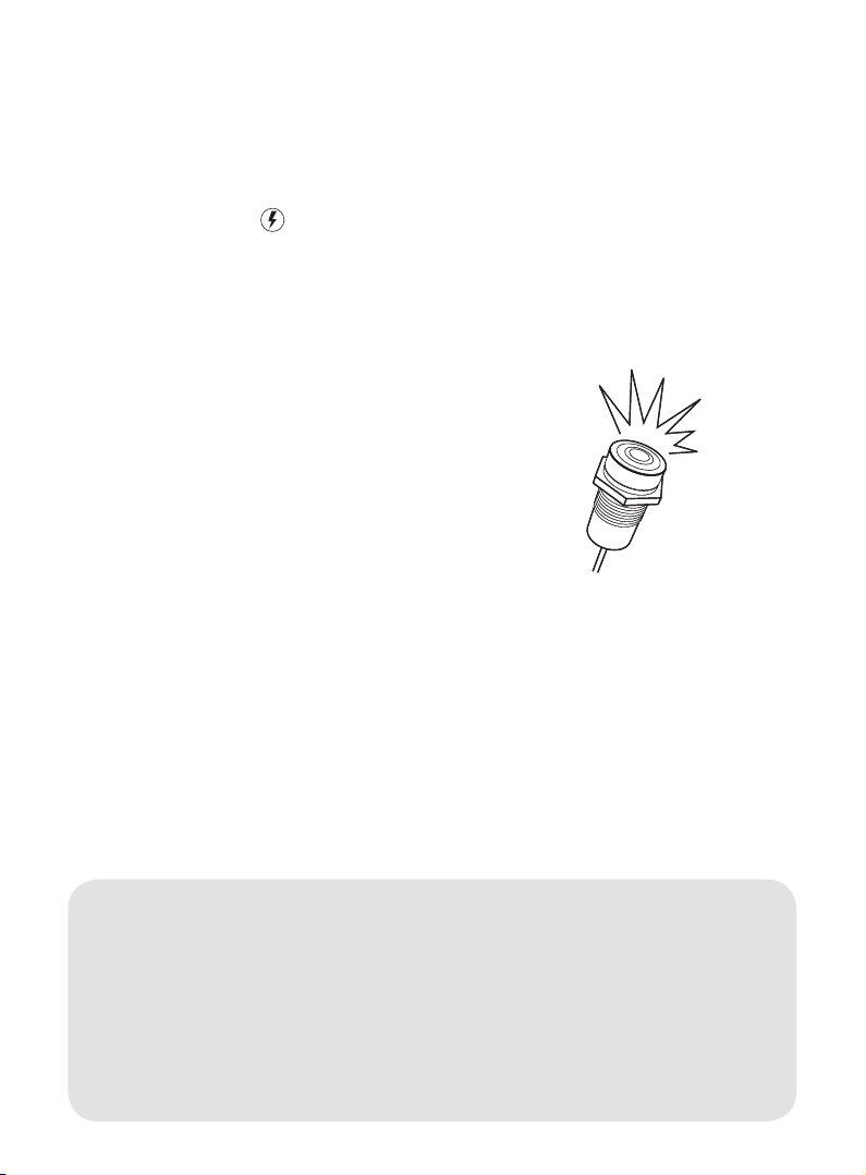
Attachthemagnetic intrusion sensor
tothedesireddoororhatch.When
thedoororhatchisclosedthegap
betweenthemagnet(nocable)and
thereedswitch(withcable)mustnot
exceed15mmtoavoidfalsealarms.
Connect the magnetic intrusion sen-
sortothecontactmarked 1on the
C-pod.
Installation Manual
2. Installing the system (continued)
max15mm
Note:Ifyouchoosenottoinstallthemagneticintrusionsensor,refer
tosection5b.
Note: Ifyouhavepurchasedoptionalaccessoriesrefertosection5b.
andtheinstructionsontheaccessory’spackaging.

10
Installation Manual
2. Installing the system (continued)
Note:Fuseandfuseholderarenotincludedinthepackage.
Note: Some optional accessories cannotbeusediftheC-podispow-
eredby24VDC.
Hint: Beforeproceeding,itisrecommendedtomeasureandverifythe
receivedvoltageonthepowerplugusingavoltmeter!
d. Power supply
TheC-podcanbepoweredby12or24VDC.Itneedsconstantpoweranditis
recommendedtoattachthepowercabledirectlytothebattery.Makesurethe
powersupplycannotbeinterruptedbyanybatteryisolationswitch.Itisadvised
toshortenthepowercabletominimizevoltagelossandgivemoreexactbat-
teryvoltagereadings.
Thecablemustbeprotectedbya1–2Afuse(slow)orathermalcircuitbreaker
mountedasclosetothepowersourceaspossible.Striptheplus(red)andminus
(black)wiresonthepowercableandconnectthemtothepowersourceusing
suitablecableconnectors/cableshoes.
11
Installation Manual
3. System start-up
Connectthepowerplugtothepow-
erportmarkedwith ontheC-pod.
TheC-podstartsup.Payattentionto
theashingoftheactivationbutton,
whichshowsthestart-upprogress.
• Theactivationbuttonashesonce
every seconduntiltheC-podhas
connectedtothestrongestavail-
ablecellular(GSM)network.
• Theactivationbuttonashesonce
every 3 secondsuntilaGPSposi-
tionhasbeenreceived.
• Theactivationbuttonashes
once every 30 seconds in normal
operatingmodetoindicatethat
thesystemisrunning.Thestart-up
sequenceiscompleted.
Foracompletelistofashpat-
ternsandtheirmeaning,referto
theReferencemanual,section
Activation Button Flashes.
Note:Thestart-upsequencenormallytakessomeminutesormore,as
theC-podscansallavailablenetworkoperatorsandreceivescongura-
tionsettings.
Hint:Beforeleavingtheboatitisrecommendedtodouble-checkthat
theinstallationandsystemstart-uphasbeensuccessfulbysendingthe
text(SMS)commandstatus or positiontotheC-podSystemNumber.
RefertotheReferencemanual,sectionText (SMS) commands.
Este manual sirve para los siguientes modelos
2
Tabla de contenidos
Manuales populares de Sistema de seguridad de otras marcas


EDM
EDM Solution 6+6 Wireless-AE Manual de usuario

Highway Safety Group
Highway Safety Group EA401 Manual de usuario

Siren
Siren LED GSM Manual de usuario

Detection Systems
Detection Systems 7090i Instrucciones de montaje

Se-Kure Controls
Se-Kure Controls MicroMini SK-4841 Manual de usuario

Siemens
Siemens FDM273 Manual de usuario